
A3 Mk2
| Oil pump, sump, balance shaft assembly - exploded view |
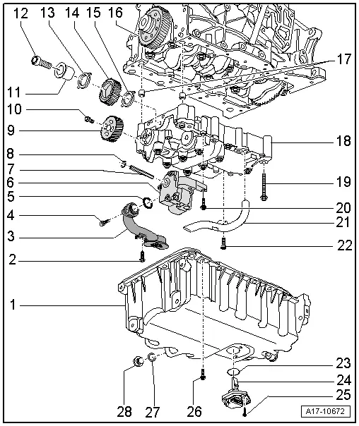
| 1 - | Sump |
| q | Removing and installing → Chapter |
| 2 - | Bolt |
| q | 20 Nm |
| 3 - | Suction pipe |
| q | Clean strainer if dirty |
| 4 - | Bolt |
| q | 9 Nm |
| 5 - | O-ring |
| q | Renew |
| 6 - | Oil pump |
| q | Removing and installing → Chapter |
| q | Before installing, check that the two dowel sleeves for centring oil pump are fitted onto balance shaft assembly |
| 7 - | Oil pump drive shaft |
| 8 - | Circlip |
| q | Must fit securely in groove |
| q | Renew circlip if damaged or stretched |
| 9 - | Spur gear for balance shaft |
| 10 - | Bolt |
| q | Renew |
| q | 20 Nm + turn 90° further |
| 11 - | Hub |
| q | For idler gear |
| q | Renew |
| 12 - | Bolt |
| q | Renew |
| q | If the bolt for the idler gear has been slackened or the spur gear on the crankshaft or the crankshaft itself have been renewed, you must install a new idler gear with the appropriate coating. Procedure for installation → Chapter „Installing a new balance shaft assembly“ |
| q | 90 Nm + turn 90° further |
| 13 - | Thrust washer |
| q | For idler gear |
| q | Only for balance shaft assembly with eight attachment points |
| q | Renew |
| 14 - | Idler gear |
| q | For balance shaft assembly |
| q | If the bolt for the idler gear has been slackened or the spur gear on the crankshaft or the crankshaft itself have been renewed, you must install a new idler gear with the appropriate coating. Procedure for installation → Chapter „Installing a new balance shaft assembly“ |
| q | To achieve the correct backlash a suitably thick coating is already applied to the new idler gear; the required clearance is achieved as the coating is worn down |
| q | Installation position: Part No. must be visible. |
| q | Make sure thrust washer -item 15- is properly seated → Fig. |
| 15 - | Thrust washer |
| q | For idler gear |
| q | Renew |
| q | Installation position → Fig. |
| q | When installing idler gear, apply grease to hold washer on balance shaft assembly |
| 16 - | Spur gear |
| q | Pulling spur gear off crankshaft and shrink-fitting new spur gear → Chapter |
| 17 - | Dowel sleeves |
| q | For centring balance shaft assembly on cylinder block |
| 18 - | Balance shaft assembly |
| q | Removing → Chapter |
| q | Before installing, check that the two dowel sleeves for centring balance shaft assembly are fitted on cylinder block |
| q | Installing new balance shaft assembly → Chapter |
| q | Re-installing "old" balance shaft assembly → Chapter |
| 19 - | Bolt |
| q | Renew |
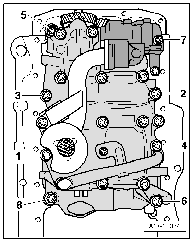
| q | Tightening torque and sequence for balance shaft assembly with eight attachment points → Fig. |
| q | Tightening torque and sequence for balance shaft assembly with six attachment points → Fig. |
| 20 - | Bolt |
| q | 9 Nm |
| 21 - | Oil intake pipe |
| 22 - | Bolt |
| q | 9 Nm |
| 23 - | Seal |
| q | Renew |
| 24 - | Oil level and oil temperature sender -G266- |
| q | Removing and installing → Chapter |
| 25 - | Bolt |
| q | Self-locking |
| q | Renew |
| q | 9 Nm |
| 26 - | Bolt |
| q | Tightening torque and sequence → Fig. |
| 27 - | Seal |
| q | Renew |
| 28 - | Oil drain plug |
| q | 30 Nm |
|
|
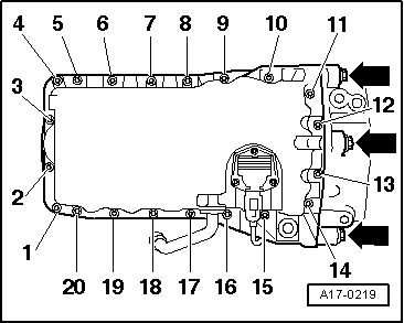
| Stage | Bolts | Tightening torque |
| 1. | -1 … 20- | 5 Nm in diagonal sequence |
| 2. | -arrows- | 40 Nm |
| 3. | -1 … 20- | Tighten in stages and in diagonal sequence; final torque 15 Nm |
 Caution
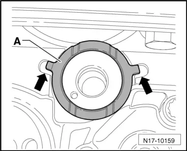
 Note
Note
|
|
| Stage | Bolts | Tightening torque |
| 1. | -1 … 8- | Screw in bolts by hand until they make contact |
| 2. | -1 … 8- | 6 Nm |
| 3. | -5- and -7- | 13 Nm |
| 4. | -1, 2, 3, 4, 6, 8- | 20 Nm |
| 5. | -1 … 8- | turn 90° further |
Note
|
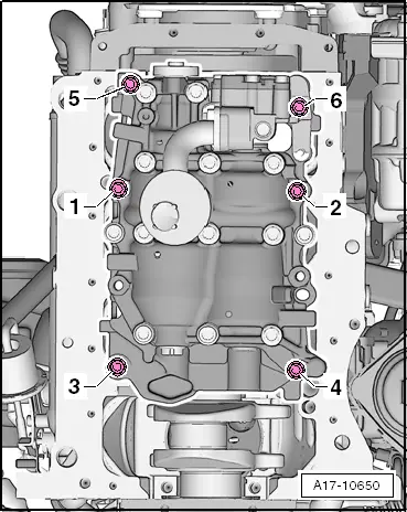
|
| Stage | Bolts | Tightening torque |
| 1. | -1 … 6- | Screw in bolts by hand until they make contact |
| 2. | -1 … 6- | 6 Nm |
| 3. | -5- and -6- | 13 Nm |
| 4. | -1 … 4- | 20 Nm |
| 5. | -1 … 6- | turn 90° further |