
A3 Mk2
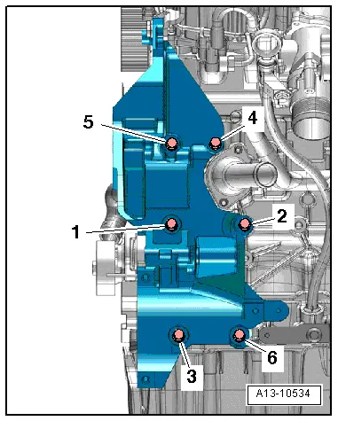
| Removing and installing bracket for ancillaries |

| Special tools and workshop equipment required |
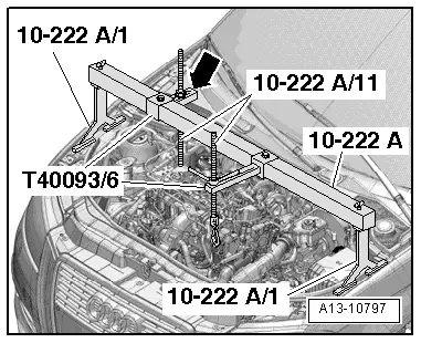
| t | Support bracket -10 - 222 A- with hexagon nut -10 - 222 A /27- |
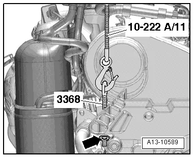
| t | Removal lever -80 - 200- |
| t | Eye-head bolt -3368- |
| t | Engine support bracket (supplementary set) -T40093- |
| t | Flange nut M10 or nut M10 with washer |
|
|
|
|
|
|
|
|
 WARNING
|
|
|
|
 Note
Note
|
|
|
|
Note
|
|