audi Workshop Repair Guides

Audi Workshop Service and Repair Manuals

Removing and installing NOx storage catalytic converter > < Wire routing on exhaust system components
Removing and installing particulate filter
Special tools and workshop equipment required
   
t  -3253/5- from assembly tool -3253-
  W00-0090
t  Tool set, 17 mm -T10395-
t  Flange bolt M10x35
Removing
–  Remove Lambda probe -G39- → Rep. gr.23.
–  Remove pressure differential sender -G505- with control pipes → Rep. gr.23.
–  Remove exhaust gas pressure sensor 1 -G450- → Rep. gr.23.
–  Remove filter → Chapter.
–  Remove exhaust gas temperature sender 2 -G448- → Chapter.
–  Remove exhaust gas temperature sender 3 -G495- → Chapter.
  W00-10767
–  Remove nuts -arrows- and detach front cross member on vehicle underside.
–  Unplug connector -1-.
  A26-10929
–  Remove nuts -1- and -2- and detach rear cross member on vehicle underside.
–  Remove centre silencer → Chapter.
  A26-0721
–  Unscrew nuts -arrows- and pull underbody cover down slightly.
  A10-10764
–  Unplug electrical connector -2- and move wiring clear.
–  Loosen clamp -1- and remove ammonia trap, exhaust flap control unit -J883- and NOx storage catalytic converter as one unit.
  A26-10933
–  Remove nuts -arrows-.
–  Remove lock washers -2- and -3-.
–  Pull inner side of cover on vehicle underside down slightly until heat shield -1- for centre tunnel can be detached.
–  Remove front right wheel.
  A26-10724
–  Remove bolts -arrows- and detach heat shield for drive shaft (right-side).
–  Unbolt drive shaft (right-side) from gearbox flange.
  A10-1633
–  Mark installation position of exhaust gas temperature sender 4 -G648--item 1-.
–  Unscrew exhaust gas temperature sender 4 -G648- from exhaust pipe behind particulate filter using a tool from tool set, 17 mm -T10395-.
  Note
Disregard -item 2-.
  A26-10937
–  Remove nuts -1- and detach bracket for particulate filter.
  A26-10723
–  Remove bolts -2- and -3- securing pendulum support.
  Note
Disregard -item 1-.
  A10-1578
–  Press engine/gearbox assembly towards lock carrier and support via pendulum support as shown in illustration.
A - Flange bolt M10x35
  Caution
Avoid damage to flexible joint.
Do NOT bend flexible joint in front exhaust pipe more than 10°.
  N34-11021
–  Remove bolts -arrows- securing bracket for exhaust system.
  A26-0735
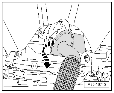
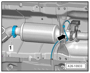
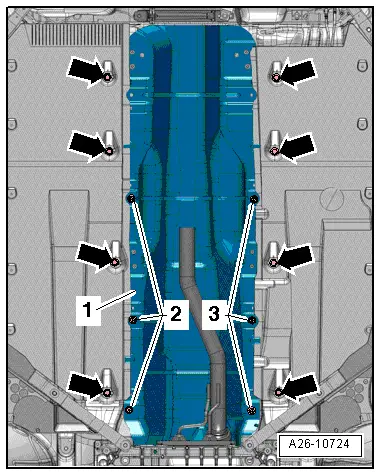
–  Remove particulate filter by rotating through 180° and about its own axis.
Installing
Installation is carried out in the reverse order; note the following:
Tightening torques
l  → Chapter „Particulate filter and NOx storage catalytic converter - exploded view“.
l  → Chapter „Exhaust flap control unit -J883- with ammonia trap - exploded view“
l  → Chapter „Centre silencer - exploded view“
l  → Chapter „Exhaust gas temperature control - exploded view“
  Note
t  Renew gaskets, self-locking nuts and clamp for particulate filter.
t  Fit all cable ties in the original positions when installing.
t  
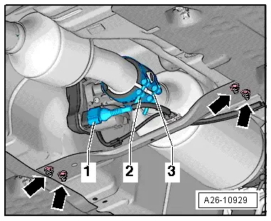
Attach exhaust gas temperature sender 4 in line with marking and secure.
–  Installation position of clamps on exhaust system → Chapter.
–  Install filter → Chapter.
–  Install underbody cover → Rep. gr.66.
–  Install pendulum support → Rep. gr.34.
–  Install drive shaft → Rep. gr.40.
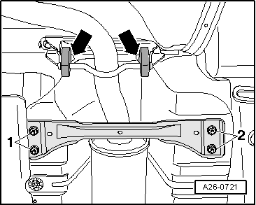
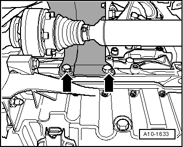
–  Install heat shield for drive shaft (right-side) → Fig..
–  Align the exhaust system so it is free of stress → Chapter.
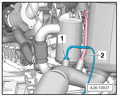
–  Install Lambda probe -G39-, exhaust gas pressure sensor 1 -G450- and pressure differential sender -G505- → Rep. gr.23.
–  After renewing particulate filter, perform Adaption in Guided Functions → Vehicle diagnostic tester.
  A26-10712

Removing and installing NOx storage catalytic converter > < Wire routing on exhaust system components