audi Workshop Repair Guides

Audi Workshop Service and Repair Manuals

Assembly mountings > < Securing engine to engine and gearbox support
Installing engine
Installing engine
Installation is carried out in the reverse order; note the following:
  Note
t  On assembly, renew oil seals and gaskets as well as self-locking nuts and bolts that are tightened by turning through to a specified angle.
t  Secure all hose connections with the correct type of hose clips (same as original equipment) → Electronic parts catalogue.
–  Check whether dowel sleeves for centring the engine/gearbox assembly are fitted in the cylinder block; install dowel sleeves if necessary.
Vehicles with manual gearbox:
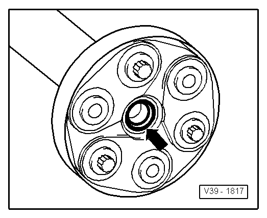
–  There should be no needle bearing fitted in the crankshaft on vehicles with manual gearbox; remove needle bearing if fitted → Chapter.
–  Check clutch release bearing for wear; renew if necessary.
–  Lubricate splines of gearbox input shaft lightly with grease for clutch plate splines -G 000 100-.
–  Check that the clutch plate is properly centralised (only necessary if you have carried out other work on the clutch).
Vehicles with direct shift gearbox:
–  A needle bearing must be fitted in the crankshaft on vehicles with direct shift gearbox; install needle bearing if not yet fitted → Chapter.
All vehicles (continued):
–  Bolt gearbox to engine.
–  Use new securing bolts.
  Note
t  Tightening torques apply only to lightly greased, oiled, phosphated or black-finished nuts and bolts.
t  Additional lubricant such as engine oil or gearbox oil may be used, but do not use lubricant containing graphite.
t  Do not use degreased parts.
t  Tolerance for tightening torques ± 15%.
   
Securing engine to manual gearbox
  A34-10035
ItemBoltNm
1 → Note, 3M12x5580
2 → NoteM12x6580
4, 5 → Note → NoteM10x5040
6 → NoteM12x8080
ADowel sleeves for centralising

1)  Bolt with M8 stud
2)  Screwed into gearbox from engine side.
3)  Retaining clip for bolt must be fitted in sump.
   
Securing engine to direct shift gearbox
  A37-0650
ItemBoltNm
1M12x5580
2 → Note → NoteM10x4040
3 → Note, 6M12x5580
4 → Note, 9M10x4540
5M12x6580
7, 8M10x5040
10M12x7080
ADowel sleeves for centralising

4)  Bolt with M8 stud
5)  Bolt is only used to secure starter to gearbox.
   
–  Install the bracket -A- for bevel box; note the following procedure:
1.  Initially tighten bolts -1- to 3 Nm.
2.  Tighten bolts -2- to 35 Nm.
3.  Then tighten bolts -1- to 45 Nm.
–  Guide engine/gearbox assembly into the body.
  A37-0655
–  Tighten bolts securing engine support to engine mounting -arrows- initially hand-tight.
  A10-1898
–  Tighten bolts securing gearbox mounting to gearbox support -arrows- initially hand-tight.
–  Use new securing bolts.
  Note
The bolts are tightened to final torque only after adjusting the engine mountings → Chapter.
–  Remove engine support from engine.
–  Install drive shafts → Rep. Gr.40.
  Note
Drive shafts must be installed prior to further assembly.
  A10-1796
–  Secure pendulum support to gearbox with new bolts -Item 2- and -Item 3-.
  A10-1578
–  Push engine/gearbox assembly towards bulkhead; the journal of the bevel box must be simultaneously inserted horizontally and carefully into the flange of the propshaft.
  Caution
The oil seal -arrow- in the flange of propshaft must not be damaged when installing the engine/gearbox assembly. The propshaft must be renewed if oil seal is damaged.
  V39-1817
–  Secure pendulum support to subframe using new bolt -item 1-.
  A10-1578
–  Secure propshaft with flexible coupling to the flange of the bevel box -arrows-.
Perform further installation in reverse order, paying attention to the following:
–  Install exhaust system and align free of stress → Chapter.
Vehicles with manual gearbox:
–  Installing and adjusting selector mechanism → Rep. Gr.34.
–  Connect pipe/hose to bleeder connection on clutch slave cylinder and bleed clutch system → Rep. Gr.30.
  Caution
The clutch pedal must not be depressed prior to bleeding the clutch system.
Vehicles with direct shift gearbox:
–  Install selector lever cable → Rep. Gr.37.
All vehicles (continued):
–  Install bracket for ancillary units → Chapter
–  To facilitate positioning of alternator, drive back bushes for securing bolts slightly.
–  Install alternator → Rep. Gr.27.
–  Install air conditioner compressor.
–  Install radiator cowl → Chapter „Removing and installing radiator fan -V7- and radiator fan 2 -V177-“.
–  Install secondary air pump → Chapter.
–  Install poly V-belt → Chapter.
–  Adjust engine mountings → Chapter.
–  Install windscreen wiper arms → Rep. Gr.92.
–  Electrical connections and routing → Current flow diagrams, Electrical fault finding and Fitting locations.
–  Connect earth strap to battery → Rep. Gr.27.
–  Check oil level → Chapter.
  Caution
Never use battery charging equipment for boost starting. There is danger of damaging the vehicle's control units.
–  Fill cooling system → Anchor.
  Note
t  Drained-off coolant may only be used again if the original cylinder head and cylinder block are re-installed.
t  Contaminated or dirty coolant must not be used again.
Tightening torques
  A10-10247
ComponentNm
Bolts/nutsM610
 M715
 M820
 M1040
 M1265
Except for the following: 
Pendulum support to gearbox40 + 90° → Note → Note
Pendulum support to subframe100 + 90° → Note → Note
Flexible coupling to flange60
Front exhaust pipe to exhaust manifold40 → Note
Drive shaft heat shield to bevel box23
Terminal B+ to starter16
Earth wire to gearbox22

6)  Renew nuts and bolts.
7)  90° = a quarter of a turn.
   

Assembly mountings > < Securing engine to engine and gearbox support