
A3 Mk2
| Timing chain - exploded view of components |
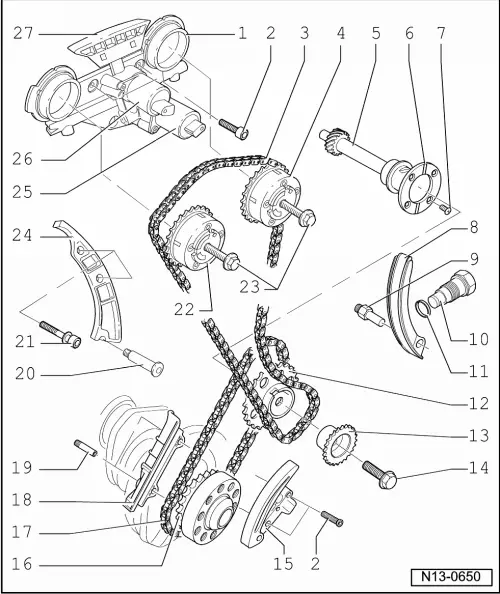
| 1 - | Valve timing housing |
| q | Removing and installing → Chapter „Removing and installing camshafts“ |
| q | Dismantling and assembling → Fig. |
| q | Check filter for dirt → Fig. |
| q | Lightly coat contact surfaces of oil seals before installing |
| 2 - | 8 Nm |
| q | Renew |
| 3 - | Camshaft timing chain |
| q | Before removing, mark running direction in colour → Fig. |
| q | Removing from camshafts → Chapter |
| q | Removing and installing → Chapter |
| 4 - | Camshaft adjuster - exhaust |
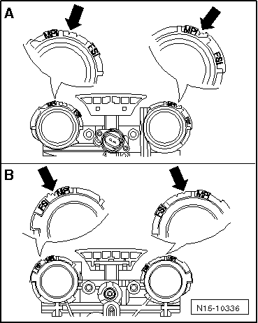
| q | Identification: “32A” |
| q | Removing and installing → Chapter |
| 5 - | Intermediate shaft |
| 6 - | Thrust washer |
| 7 - | 8 Nm |
| q | Apply locking fluid when installing; refer to → Electronic parts catalogue |
| 8 - | Tensioning rail for timing chain |
| q | To remove and install it is first necessary to remove both the upper and lower covers for the timing chains |
| 9 - | Pivot pin |
| 10 - | Chain tensioner for camshaft timing chain -40 Nm- |
| q | Removing and installing → Chapter |
| 11 - | Oil seal |
| q | Renew if damaged or leaking |
| 12 - | Sprocket for drive chain for valve gear |
| q | Removing and installing → Chapter |
| 13 - | Sprocket for camshaft timing chain |
| q | Removing and installing → Chapter |
| 14 - | 60 Nm + turn 90° further |
| q | Renew |
| q | When loosening and tightening use tool -T10069- to counterhold on vibration damper. |
| 15 - | Chain tensioner with tensioning rail |
| q | For drive chain |
| q | Before installing, release locking spline in chain tensioner with a small screwdriver and press tensioning rail against chain tensioner |
| 16 - | Drive chain sprocket |
| q | Integral part of crankshaft |
| 17 - | Drive chain for valve gear |
| q | Mark rotation direction before removing → Fig. |
| q | Removing and installing → Chapter |
| 18 - | Guide rail for drive chain for valve gear |
| q | Removing and installing → Chapter |
| 19 - | Pin, 10 Nm |
| q | For guide rail |
| 20 - | 18 Nm |
| 21 - | 23 Nm |
| 22 - | Camshaft adjuster - inlet |
| q | Identification: “24E” |
| q | Removing and installing → Chapter |
| 23 - | Bolt |
| q | Renew |
| q | Contact surface of sender wheel at bolt head must be dry when installing. |
| q | To loosen and tighten, counterhold with open-end spanner on hexagon flats of camshaft → Chapter |
| q | 60 Nm + 90° (1/4 turn further) |
| 24 - | Guide rail for camshaft timing chain |
| q | Removing and installing → Chapter |
| 25 - | Inlet camshaft control valve 1 -N205- |
| q | For inlet camshaft |
| q | Mark electrical connector before disconnecting |
| 26 - | Exhaust camshaft control valve 1 -N318- |
| q | For exhaust camshaft |
| q | Mark electrical connector before disconnecting |
| 27 - | Guide rail for camshaft timing chain |
| q | Clipped onto valve timing housing |
 Caution
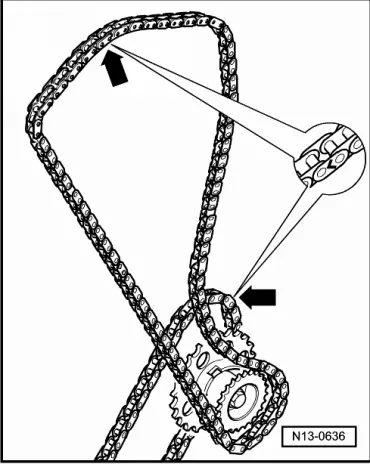
|
|