
A3 Mk2
| Crankshaft - exploded view of components |
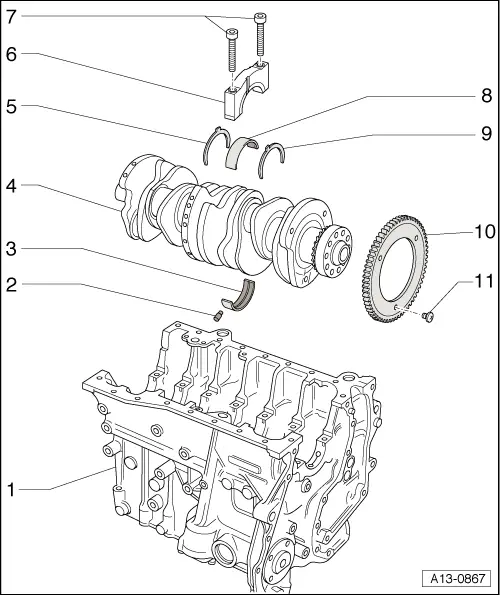
| 1 - | Cylinder block |
| q | Checking cylinder bore → Fig. |
| q | Piston and cylinder dimensions → Chapter |
| 2 - | Oil spray jet (for cooling of pistons) |
| q | For crankshaft bearings 2 ... 7 |
| q | Opening pressure: 2.0 bar |
| q | Removing and installing → Fig. |
| 3 - | Bearing shell |
| q | For cylinder block, with oil supply drilling |
| q | Do not interchange used bearing shells (mark positions) |
| q | Only supplied as a replacement part with “yellow” marking |
| 4 - | Crankshaft |
| q | After removing, place it down so that the sender wheel → Item does not become damaged |
| q | Axial clearance when new: 0.07 ... 0.23 mm; Wear limit: 0.30 mm |
| q | Check radial clearance with Plastigage |
| q | Do not rotate the crankshaft when checking the radial clearance |
| q | Radial clearance when new: 0.02 ... 0.06 mm; wear limit 0.10 mm |
| q | Crankshaft dimensions → Chapter |
| q | Chain sprocket is an integral part of crankshaft |
| 5 - | Thrust washer |
| q | For bearing No. 5 |
| q | Note location |
| q | Oil groove points towards crankshaft |
| 6 - | Bearing cap |
| q | Bearing cap 1: Pulley end |
| q | Bearing cap 5 with recesses for thrust washers |
| q | Bearing shell retaining lugs (cylinder block/bearing cap) must be on the same side |
| 7 - | 30 Nm +180° (1/2 turn) further |
| q | Renew |
| 8 - | Bearing shell |
| q | For bearing cap, without drilling |
| q | Do not interchange used bearing shells (mark positions) |
| q | Only supplied as a replacement part with “yellow” marking |
| 9 - | Thrust washer |
| q | For bearing No. 5 |
| q | Note location |
| q | Oil groove points towards crankshaft |
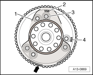
| 10 - | Sender wheel |
| q | For engine speed sender -G28- |
| q | Sender wheel must be renewed if bolts are loosened |
| q | Installing → Fig. |
| 11 - | 10 Nm + 90° (1/4 turn) further |
| q | Renew |
| q | Sender wheel must be renewed if bolts are loosened → Fig. |
|
|
| Component | Nm |
| Sender wheel to crankshaft | 10 + 90° → Note |
|