| –
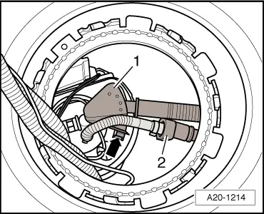
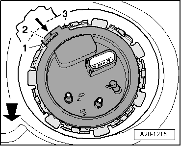
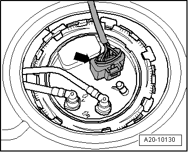
| Carefully pull fuel gauge sender 2 -G169--item 2- together with suction-jet pump -1- just slightly out of opening in fuel tank. |
| –
| Unclip suction-jet pump from flange -arrows-. |

Note | When removing, make sure you do not bend float arm of fuel gauge sender 2 -G169-. |
| –
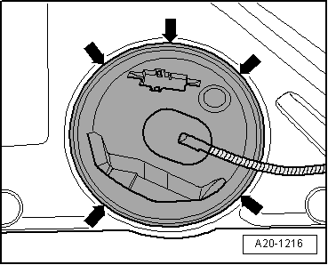
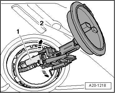
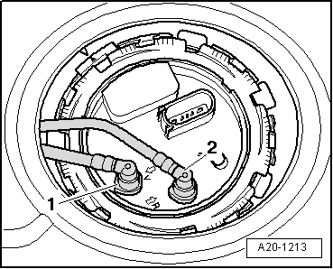
| Reach into fuel tank opening on left side of vehicle and pull out suction-jet pump, with pipes pointing towards the left. |
| Installation is carried out in the reverse order; note the following: |
Note | t
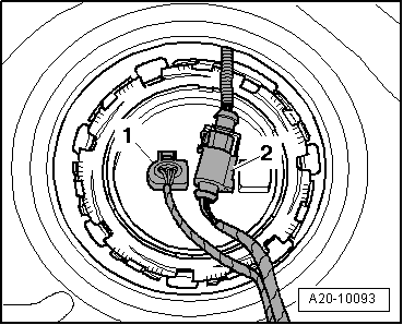
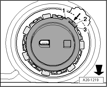
| When installing, make sure you do not bend float arm of fuel gauge sender 2 -G169-. |
| –
| Push suction-jet pump (with pipes attached) into fuel tank opening on left side of vehicle. |
|
|
|

 Caution
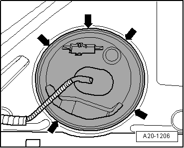
 WARNING