
A4 Cabriolet Mk2
 Note
Note
|

| 1 - | (Function selection switch -E91- or function selection switch II -E272-) |
| q | Rotary knob/pushbutton in centre console (rotary knob/pushbutton in centre console gradually being discontinued on vehicles as of Model Year 2005) |
| q | On vehicles as of Model Year 2005, entry in control unit in dash panel insert -J285- is made by way of switch at windscreen wiper stalk on steering column (gradual discontinuation of rotary knob/pushbutton in centre console) |
| q | This function selection switch is used to enter the various auxiliary heating/auxiliary ventilation actuation functions in the control unit in dash panel insert -J285- → Chapter |
| 2 - | Operating and display unit, Climatronic control unit -J255- |
| q | In other repair documentation, this component may also be referred to as air conditioning system/Climatronic operating and display unit -E87-. |
| q | For air conditioner or heater |
| q | Actuated by way of convenience data bus system |
| q | When operating auxiliary heater by way of “Timer” function or remote control, this unit determines auxiliary heater start-up mode (auxiliary ventilation or auxiliary heating) on vehicles with air conditioner. → Air conditioning; Rep. Gr.01 (adaption of operating and display unit, Climatronic control unit -J255-). |
Note| Depending on the version of the operating and display unit, Climatronic control unit -J255-, when activation is implemented by way of the “Auxiliary heating/auxiliary ventilation” function, a certain minimum permissible temperature (e.g. 20 °C) is selected as specified temperature by the operating and display unit, Climatronic control unit -J255- irrespective of the setting and used for control purposes. |
| 3 - | Circulation pump -V55- (fitting location e.g. on vehicles with 4-cyl. TDI engine) |
| q | Checking → Chapter |
| q | Removing and installing → Chapter |
| 4 - | Auxiliary heater (horizontal installation, fitting location e.g. on vehicles with 4-cyl. TDI engine) |
| q | Removing and installing → Chapter |
| q | Incorporation into coolant circuit → Chapter |
| q | Dismantling and assembling → Chapter |
| q | Further notes → Item |
| 5 - | Auxiliary heater control unit -J364- (fitting location e.g. on vehicles with 4-cyl. TDI engine) |
| q | Removal and installation involve detaching the auxiliary heater from the vehicle → Chapter |
| q | Replacing → Chapter |
| q | If the auxiliary heater control unit -J364- is replaced, the function of at least one hand transmitter is to be checked on vehicles with “auxiliary heater remote control” as optional extra; all hand transmitters must be re-adapted if necessary → Chapter |
| q | On replacement, pay attention to correct version (different models for petrol and diesel) → Chapter, → Chapter (adaption channel “05”) and → Parts List |
| In auxiliary heating mode, the metering pump -V54- is actuated with full voltage by the auxiliary heater control unit -J364- up to control unit part number index “B”. For control units as of part number index “C” (gradual introduction as of Model Year 2005), the voltage for the actuation signal of the metering pump -V54- will be limited in auxiliary heating mode to 9.2 V with the petrol version and 9.8 V with the diesel version, thus reducing the operating noise of the metering pump -V54-. |
| 6 - | Heater coolant shut-off valve -N279- |
| q | Actuated in auxiliary heating mode by auxiliary heater control unit -J364- |
| q | Removing and installing → Chapter |
Note| t | Currently only actuated on vehicles with 6-cyl. engine. |
| t | Vehicles with 4-cyl. engine are not provided with a heater coolant shut-off valve -N279- at present. Vehicles manufactured up to Model Year 2005 may be fitted with a shut-off valve, but this is not actuated (the auxiliary heater control unit -J364- must be encoded accordingly) → Chapter (Encoding auxiliary heater). |
| t | At the start of production (up to Model Year 2004), vehicles with 4-cyl. engine were fitted with the heater coolant shut-off valve -N279-. However, in view of the fact that cold starting problems may be encountered with these engines at very low ambient temperatures following auxiliary heating operation with a small coolant circuit (engine is only slightly pre-heated), the auxiliary heater control unit -J364- is to be encoded such that the heater coolant shut-off valve -N279- is not actuated. |
| 7 - | Auxiliary heater control unit -J364- (fitting location e.g. on vehicles with 6-cyl. engine) |
| q | Removal and installation involve taking out the auxiliary heater |
| q | Replacing → Chapter |
| q | If the auxiliary heater control unit -J364- is replaced, the function of at least one hand transmitter is to be checked on vehicles with “auxiliary heater remote control” as optional extra; all hand transmitters must be re-adapted if necessary → Chapter |
| q | On replacement, pay attention to correct version (different models for petrol and diesel) → Chapter, → Chapter (adaption channel “05”) and → Parts List |
| In auxiliary heating mode, the metering pump -V54- is actuated with full voltage by the auxiliary heater control unit -J364- up to control unit part number index “B”. For control units as of part number index “C” (gradual introduction as of Model Year 2005), the voltage for the actuation signal of the metering pump -V54- will be limited in auxiliary heating mode to 9.2 V with the petrol version and 9.8 V with the diesel version, thus reducing the operating noise of the metering pump -V54-. |
| 8 - | Circulation pump -V55- (fitting location e.g. on vehicles with 6-cyl. engine) |
| q | Removal and installation involve taking out the auxiliary heater → Chapter |
| q | Checking → Chapter |
| q | Removing and installing → Chapter |
| 9 - | Auxiliary heater (vertical installation, fitting location e.g. on vehicles with 6-cyl. engine) |
| q | Removing and installing → Chapter |
| q | Incorporation into coolant circuit → Chapter |
| q | Dismantling and assembling → Chapter |
| q | Checking auxiliary heater electrical components → Chapter |
| q | Block diagram of auxiliary heater → Chapter |
Note| t | On replacement, pay attention to correct version (different models for petrol and diesel) → Chapter → Parts List. |
| t | The auxiliary heater is fitted with the following electrical components: |
| t | - Combustion air blower -V6- |
| t | - Glow plug for heater -Q9-. |
| t | - Heater overheating fuse -S24- |
| t | - Flame monitor -G64- |
| t | - Temperature sensor -G18- |
| 10 - | Control unit in dash panel insert -J285- |
| q | The various auxiliary heating/auxiliary ventilation actuation functions are set by way of the function selection switch, item → Item. |
| q | If auxiliary heater remote control is fitted as an optional extra, this actuates the auxiliary heater control unit, which in turn transmits the information “Switch auxiliary heating/auxiliary ventilation on or off” via the convenience data bus system to the control unit in dash panel insert -J285-. Further information → Chapter |
| q | The “auxiliary heater” optional extra must have been adapted by way of the “Adaption” function in the control unit in dash panel insert -J285- → Electrical system; Rep. Gr.01 and → "Guided fault-finding" function of vehicle diagnostic, testing and information system VAS 5051. |
| q | If there is insufficient fuel in the fuel tank (fuel gauge in red zone), the auxiliary heater cannot be switched on (tick in driver information system for “Immediate auxiliary heater activation” function cannot be activated or goes out again). Depending on the version of the control unit in dash panel insert -J285-, it may however still be possible to activate the auxiliary heater by way of the “Immediate heating” function but not using the “Timer” function and remote control. |
| q | When operating the auxiliary heater by way of the “Timer” function or remote control, this unit determines the auxiliary heater start-up mode (auxiliary ventilation or auxiliary heating) on vehicles with no air conditioner. → Electrical system; Rep. Gr.01 and → "Guided fault-finding" function of vehicle diagnostic, testing and information system VAS 5051. |
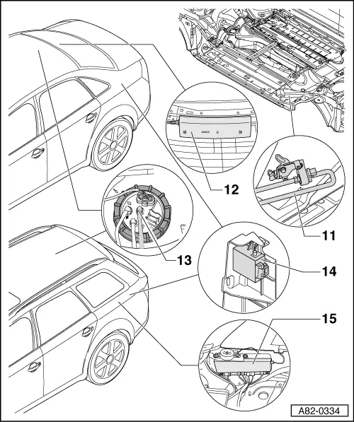
| 11 - | Metering pump -V54- |
| q | Removing and installing → Chapter |
| q | Diverting fuel for auxiliary heater → Chapter |
| q | Checking fuel delivery → Chapter |
| q | Checking actuation → Chapter |
| In auxiliary heating mode, the metering pump -V54- is actuated with full voltage by the auxiliary heater control unit -J364- up to control unit part number index “B”. For control units as of part number index “C” (gradual introduction as of Model Year 2005), the voltage for the actuation signal of the metering pump -V54- will be limited in auxiliary heating mode to 9.2 V with the petrol version and 9.8 V with the diesel version, thus reducing the operating noise of the metering pump -V54-. |
| 12 - | Aerial selection control unit (Saloon, Coupe) |
| q | Different versions depending on vehicle equipment |
| q | With additional connection for aerial wire to auxiliary heating radio controlled receiver -R64- → Chapter and → Radio, telephone, navigation; Rep. Gr.91 |
| 13 - | Fuel delivery unit |
| q | Different fuel delivery units depending on vehicle model and production period (petrol or diesel engine, FWD or 4WD) → Fuel supply system; Rep. Gr.20 |
| q | With connection for diverting fuel to auxiliary heater (vehicles with auxiliary heater only) → Fuel supply system; Rep. Gr.20 |
| q | Diverting fuel for auxiliary heater → Chapter |
| 14 - | Auxiliary heating radio controlled receiver -R64- |
| q | Not installed in all vehicles, optional extra → Chapter |
| q | Fitting location, removing and installing → Chapter and → Radio, telephone, navigation; Rep. Gr.91 |
| q | If the auxiliary heating radio controlled receiver -R64- is replaced, all auxiliary heater remote control hand transmitters have to be matched to the auxiliary heating radio controlled receiver -R64- (by way of the auxiliary heater control unit -J364-) → Chapter |
| 15 - | Left aerial module -R108- (Avant) |
| q | Different versions depending on vehicle equipment |
| q | With additional connection for aerial wire to auxiliary heating radio controlled receiver -R64- → Chapter and → Radio, telephone, navigation; Rep. Gr.91 |