audi Workshop Repair Guides

Audi Workshop Service and Repair Manuals

Removing and installing flange shaft (right-side) > < Servicing front final drive
Removing and installing flange shaft (left-side)
Special tools and workshop equipment required
t  Drip tray
   
Removing
Vehicles with V6 petrol engine:
–  Pull off rear engine cover panel -arrows-.
  A10-1032
–  Remove cover -1- on left side of engine compartment.
  A10-1031
–  Unbolt coolant expansion tank -arrow-.
–  Unplug electrical wiring leading to coolant shortage indicator switch -F66- at expansion tank (bottom) and tie expansion tank clear to one side (with coolant hoses -1...3- attached).
  A10-0989
–  If fitted, remove heat shield for connectors from left of bulkhead.
–  Detach electrical connectors -1 ... 4- from retainer at left of bulkhead.
–  Unplug electrical connectors -1- and -4-.
–  Move Lambda probe wires clear.
–  Remove retainer for connectors.
  A10-1002
–  Unscrew nut -2- (accessible from above), connecting front exhaust pipe to exhaust manifold on left side.
  Note
t  For illustration purposes here shown with engine removed.
t  The nuts -1- and -3- (accessible from below) are removed at a later stage.
  A26-0439
Continued for all vehicles:
–  Remove front left wheel.
–  On vehicles fitted with auxiliary heater, remove screws -arrows- securing exhaust pipe of auxiliary/ additional heater to noise insulation.
  A10-0407
–  Release fasteners -1 ... 3- and detach noise insulation panels (front -A- and - if fitted- rear -B-).
  A34-0530
–  If fitted, unbolt heat shield for left-side drive shaft -arrows-.
–  Remove drive shaft -1- (left-side) from gearbox flange shaft and tie up to on side as high as possible.
  Note
Make sure you do not damage surface coating on drive shaft.
  A34-0138
Vehicles with V6 petrol engine:
–  Unscrew bolts -1 ... 4- and remove front cross piece, if fitted.
  Note
  A26-0568
The flexible joint (de-coupling element) on the front exhaust pipe must not be bent more than 10° – otherwise it can be damaged.
–  Disconnect exhaust system at clamp (left-side) -left arrow-.
  A26-0437
–  Unscrew nuts -1- and -3- (accessible from below) connecting front exhaust pipe to exhaust manifold on left side.
  Note
For illustration purposes here shown with engine removed.
–  Detach front exhaust pipe from exhaust manifold on left side and remove front section of exhaust system.
  A26-0439
Vehicles with V6 TDI engine:
–  Remove nuts -arrows-.
  A26-10122
–  Remove bolt -1-.
  A26-10120
–  If fitted, remove front cross piece -1--arrows-.
  Note
The flexible joint (de-coupling element) on the front exhaust pipe must not be bent more than 10° – otherwise it can be damaged.
–  Release clamp -2- and remove front exhaust pipe with catalytic converter -3-.
  A34-0509
Continued for all vehicles:
–  Place drip tray beneath gearbox.
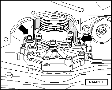
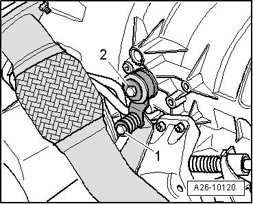
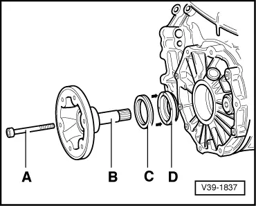
–  Remove bolt -A- securing flange shaft -B-. To do so, screw two bolts into flange and counterhold flange shaft with suitable lever.
  Note
Ignore -item C- and -item D-.
–  Pull out flange shaft.
Installing
Installation is carried out in reverse sequence; note the following:
–  Install flange shaft.
–  Bolt drive shaft to gearbox flange → Rep. Gr.40.
Vehicles with V6 engine:
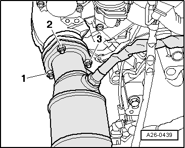
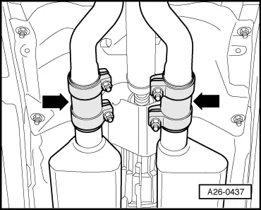
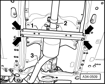
–  Install front exhaust pipe and perform stress-free alignment → Rep. Gr.26.
–  If fitted, install front cross piece → Rep. Gr.66.
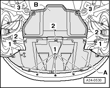
–  Install heat shield for drive shaft.
Continued for all vehicles:
–  Fill manual gearbox with gear oil and check oil level → Chapter.
Tightening torques
  V39-1837
ComponentsNm
Flange shaft to gearbox10 + 90° 1)
Heat shield for drive shaft to gearbox23
l  1) 90° is equivalent to a quarter turn.


Removing and installing flange shaft (right-side) > < Servicing front final drive