audi Workshop Repair Guides

Audi Workshop Service and Repair Manuals

Renewing oil seal for flange shaft > < Removing and installing flange shaft (left-side)
Removing and installing flange shaft (right-side)
Special tools and workshop equipment required
t  Drip tray
   
Removing
Vehicles with V6 petrol engine:
–  Pull off rear engine cover panel -arrows-.
  A10-1032
–  Remove cover -1- on right side of engine compartment.
  A10-1030
–  Remove bolts -arrows-.
–  Disengage activated charcoal filter solenoid valve 1 -N80--item 1- at air duct.
–  Remove air duct -2-.
  A10-0900
–  Remove air cleaner housing -arrows-.
  A26-0444
–  Remove bolts -arrows- from solenoid valve mounting plate -3-.
–  Detach electrical connector at air mass meter -G70-.
–  Detach crankcase breather hose -4- from air duct -2-.
  A34-0460
–  Unscrew bolt -arrow- and disconnect air duct -2- from throttle valve module -J338-.
–  If fitted, detach hose -1- from air duct.
  Note
For illustration purposes here shown from rear, with engine removed.
  A34-0461
–  Detach electrical connectors -1 ... 4- from retainer at right of bulkhead.
–  Unplug electrical connectors -1- and -4-.
–  Move Lambda probe wires clear.
–  Remove retainer for connectors.
  A10-1003
–  Unscrew nut -2- (accessible from above), connecting front exhaust pipe to exhaust manifold on right side.
  Note
t  For illustration purposes here shown with engine removed.
t  The nuts -1- and -3- (accessible from below) are removed at a later stage.
  A26-0440
Continued for all vehicles:
–  Remove front right wheel.
–  On vehicles fitted with auxiliary heater, remove screws -arrows- securing exhaust pipe of auxiliary/ additional heater to noise insulation.
  A10-0407
–  Release fasteners -1 ... 3- and detach noise insulation panels (front -A- and - if fitted- rear -B-).
  A34-0530
Vehicles with V6 petrol engine:
–  Unscrew bolts -1 ... 4- and remove front cross piece, if fitted.
  Note
  A26-0568
The flexible joint (de-coupling element) on the front exhaust pipe must not be bent more than 10° – otherwise it can be damaged.
–  Disconnect exhaust system at clamp (right-side) -right arrow-.
  A26-0437
–  Unscrew nuts -1- and -3- (accessible from below) connecting front exhaust pipe to exhaust manifold on right side.
  Note
For illustration purposes here shown with engine removed.
–  Detach front exhaust pipe from exhaust manifold on right side and remove front section of exhaust system.
  A26-0440
Vehicles with 4-cylinder TDI engine:
–  Remove noise insulation -1- in wheel housing (right-side).
  A10-10179
Continued for all vehicles:
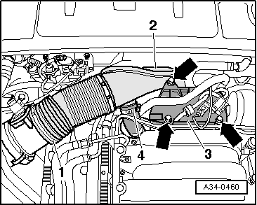
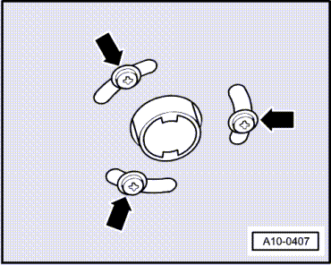
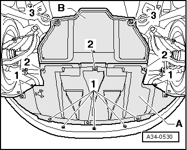
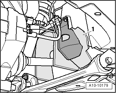
–  If fitted, unbolt heat shield for right-side drive shaft -arrows-.
–  Remove drive shaft -1- (right-side) from gearbox flange shaft and tie up to on side as high as possible.
  Note
Make sure you do not damage surface coating on drive shaft.
–  Place drip tray beneath gearbox.
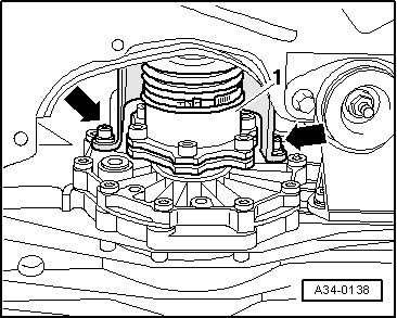
–  Remove bolt securing flange shaft. To do so, screw two bolts into flange and counterhold flange shaft with suitable lever.
–  Pull out flange shaft.
Installing
Installation is carried out in reverse sequence; note the following:
–  Install flange shaft.
–  Bolt drive shaft to gearbox flange → Rep. Gr.40.
Vehicles with V6 petrol engine:
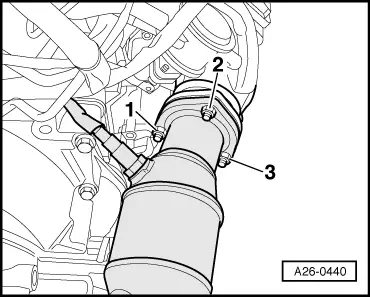
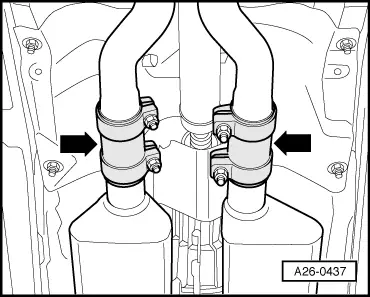
–  Install front exhaust pipe and perform stress-free alignment → Rep. Gr.26.
Continued for all vehicles:
–  If fitted, install front cross piece → Rep. Gr.66.
–  Install heat shield for drive shaft.
–  Fill manual gearbox with gear oil and check oil level → Chapter.
Tightening torques
  A34-0138
ComponentsNm
Flange shaft to gearbox10 + 90° 1)
Heat shield for drive shaft to gearbox23
l  1) 90° is equivalent to a quarter turn.


Renewing oil seal for flange shaft > < Removing and installing flange shaft (left-side)