| –
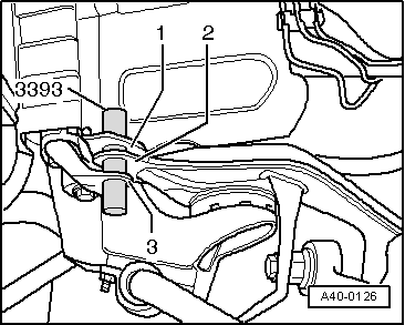
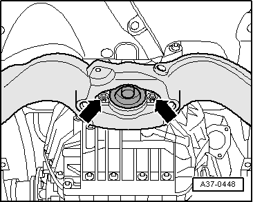
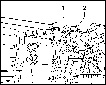
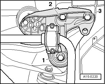
| Tighten nuts -1- for engine mountings. |
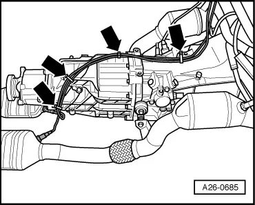
| The remaining installation steps are carried out in the reverse sequence; note the following points: |
| –
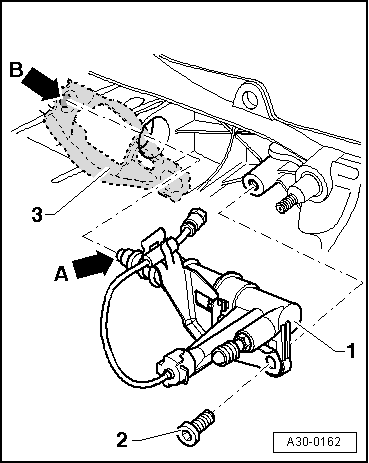
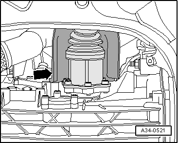
| Check selector mechanism setting and adjust if necessary → Chapter. |

Note | t
| Tightening torques apply only to lightly greased, oiled, phosphated or black-finished nuts and bolts. |
| t
| Additional lubricant such as engine or gearbox oil may be used, but do not use graphite lubricant. |
| t
| Do not use parts which have been degreased. |
| t
| Tolerance for tightening torques ±15%. |
|
|
|

 Caution
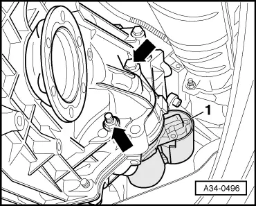
 WARNING