
A4 Cabriolet Mk2
| Removing gearbox - vehicles with 2.5 ltr. TDI engine |

| Special tools and workshop equipment required |
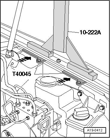
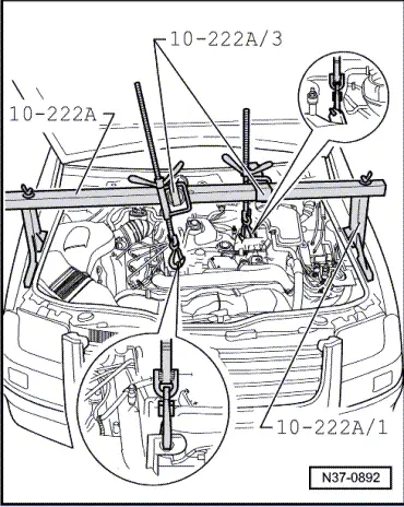
| t | Support bracket -10-222 A- |
| t | Rack -10-222 A /1- |
| t | Adapter -10-222 A /3- |
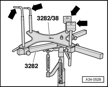
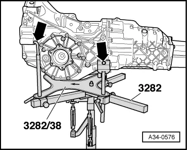
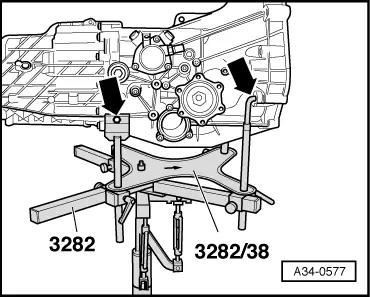
| t | Gearbox support -3282- |
| t | Adjustment plate -3282/38- |
| t | Mounts -3282/49- (2x) |
| t | Mounts -3282/52- (2x) |
|
|
|
|
 Note
Note
|
|
 Caution
|
|
|
|
|
|
|
|
|
|
|
|
|
|
|
|
|
|
|
|
Note
|
|
|
|
|
|
Note
|
|
|
|
|
|
|
|
|
|
|
|
|
|
|
|
|
|
Note
|
|
|
|
Note
|
|
|
|
|
|
|
|
|
|
Note
|
|
|
|
|
|
|
|
Note
Note
|
|
|
|