audi Workshop Repair Guides

Audi Workshop Service and Repair Manuals

Installing gearbox - vehicles with 4-cylinder TDI engine > < Removing and installing gearbox
Removing gearbox - vehicles with 4-cylinder TDI engine
   
Removing gearbox - vehicles with 4-cylinder TDI engine
Special tools and workshop equipment required
t  Support bracket -10-222 A-
t  Gearbox support -3282-
t  Adjustment plate -3282/43-
t  Torque wrench -V.A.G 1331-
t  Torque wrench -V.A.G 1332-
t  Engine and gearbox jack -V.A.G 1383 A-

   
t  Wing compensation plate -T40045-
t  Grease for clutch plate splines -G 000 100-
t  Copper grease -Z 381 351 TE-
Procedure
  Note
All cable ties which are released or cut open during removal must be fitted in the same position when installing.
  Caution
Follow steps required when disconnecting battery → Electrical system; Rep. Gr.27.
  W00-1401
–  With ignition switched off, disconnect battery earth strap -arrow-.
  A27-0098
–  Pull off engine cover panel -arrows-.
  A10-10294
–  Unbolt coolant expansion tank -arrow-.
–  Unplug electrical connector for coolant shortage indicator switch -F66- at expansion tank (bottom) and move coolant expansion tank (with coolant hoses -1 … 3- attached) clear to one side.
  A10-0989
–  Move clear electrical wiring at fuel filter bracket.
–  Unscrew nuts -arrows- and move fuel filter aside (with fuel hoses attached).
  A10-10285
–  Remove upper engine/gearbox securing bolts -arrows 1- and -arrows 2-. Please note that there may be brackets for wires/lines located beneath the bolts -arrows 2- (important for installation).
  A34-0704
–  Detach rubber seal from edges of wing mounting flanges.
–  To avoid damaging edges of wing panels with support bracket -10-222 A-, insert wing compensation plates -T40045- on both sides between the wing mounting flange and the body panel underneath.
  A19-0412
–  Position support bracket -10-222 A- on wing mounting flange with adapters -10-222A/3-.
–  Engage spindles on engine lifting eyes as illustrated.
–  Take up weight of engine using spindles.
  A10-10993
–  On vehicles fitted with auxiliary heater, remove screws -arrows- securing exhaust pipe of auxiliary/ additional heater to noise insulation.
  A10-0407
–  Release quick-release fasteners -1 ... 3- and detach noise insulation panels (front -A- and rear -B-).
  A34-0530
–  Detach bracket -arrow- for noise insulation.
  N34-0588
–  Slacken nuts -arrows- at stop for torque reaction support, but do not remove.
  A10-10288
–  Remove noise insulation -1- in wheel housing (right-side).
  A10-10179
–  Unbolt heat shield -arrow- for drive shaft (right side) from gearbox.
–  Unbolt drive shafts (left and right) from gearbox flange shafts.
  A34-0521
–  If fitted, remove engine speed sender -G28- on left side of gearbox.
  A34-0119
–  Unscrew temperature sender after particulate filter -G527--item 1-.
–  Unscrew nuts -arrows- and remove front exhaust pipe behind particulate filter → Rep. Gr.26.
  A26-10499
–  Remove bolts -arrows- at gearbox/propshaft flange.
–  Slide propshaft together towards rear final drive. The constant velocity joints can be moved axially.
–  Tie propshaft to side.
  A34-10146
–  Unscrew the three lower engine/gearbox securing bolts -arrow-.
  A34-0433
–  Detach starter from engine/gearbox and secure if necessary → Electrical system; Rep. Gr.27.
  Note
Starter cables do not have to be disconnected.
  N34-0589
–  Drill a hole of 10.2 mm Ø -arrow- in supporting element of gearbox support -3282-.
  A34-0527
–  To remove manual gearbox 0A3, four-wheel drive, set up gearbox support -3282- with adjustment plate -3282/38- and place on engine and gearbox jack -V.A.G 1383 A-.
  Note
t  The positions of the support elements -arrows- are shown on the adjustment plate in schematic form (the arrow points in direction of travel).
t  The adjustment plate can only be fitted in one position.
  A34-0528
–  Align the adjustment plate parallel to the gearbox.
–  Secure the supporting elements to the left side of the gearbox, as shown in illustration. Tighten bolt M10x20 -arrow on right side- to 20 Nm.
  A34-0576
–  Secure the supporting elements to the right side of the gearbox, as shown in illustration. Tighten bolt M10x20 -arrow on left side- to 20 Nm.
  A34-0577
–  First remove bolts -1- and then bolts -2- at tunnel cross member.
  A34-10147
–  Unscrew nuts -arrows- and detach tunnel cross member.
  A37-0448
–  Slowly lower rear of gearbox with engine and gearbox jack -V.A.G 1383 A-.
  Note
Do not lower the gearbox too far: the distance between the subframe and the body (dimension -a-) must not be more than 60 mm.
  A10-10106
–  Re-tension front spindle -10 - 222 A /11- slightly (do not lift engine while doing so).
  A34-10016
–  Detach push rod -1-; to do so, unscrew hexagon socket head bolt.
–  Unscrew connecting rod -2- for selector rod.
  N34-1208
–  Unscrew nut -1- and pull gearbox selector lever -2- off gearbox selector shaft.
  A34-0140
–  Remove remaining engine/gearbox securing bolts -arrow A- and -arrow B-.
  A34-0434
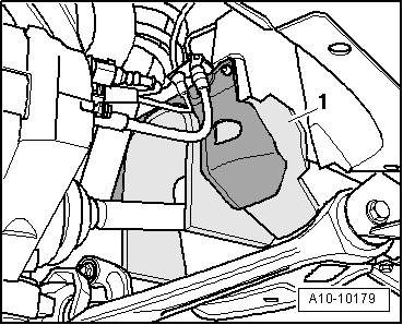
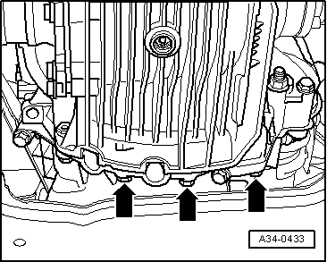
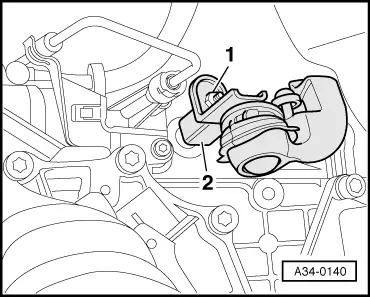
–  Press gearbox off dowel sleeves and lower carefully with engine and gearbox jack -V.A.G 1383 A- just far enough to gain access to the clutch slave cylinder.
  Note
When lowering gearbox, ensure hydraulic line to clutch slave cylinder is not damaged.
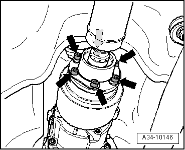
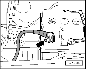
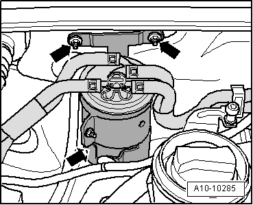
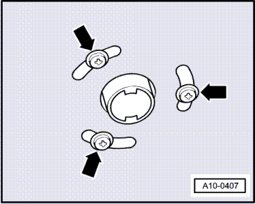
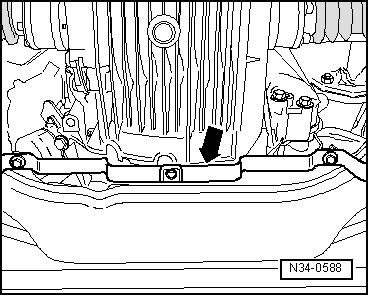
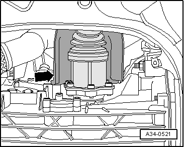
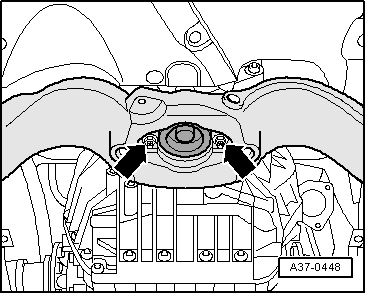
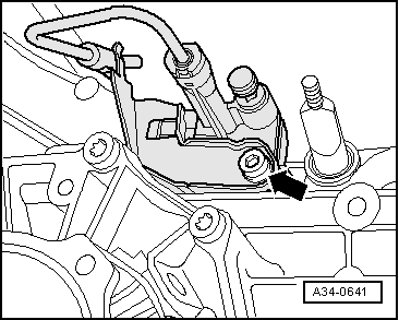
–  Detach clutch slave cylinder from gearbox -arrow- and secure with wire; do not open pipe/hose system.
  Caution
Do not depress clutch pedal after removing slave cylinder. The slave cylinder would then be destroyed once pedal force exceeds approx. 300 N.
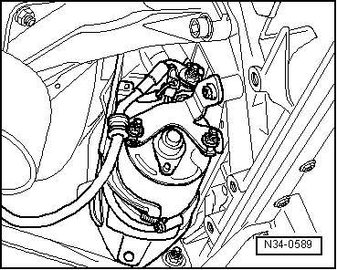
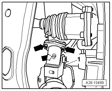
–  If fitted, move clear electrical wiring at top of gearbox.
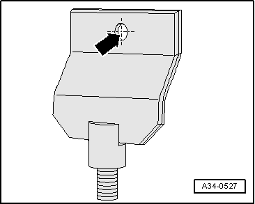
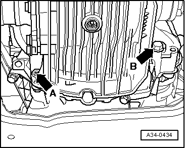
–  Lower gearbox completely.
  Note
When lowering gearbox, make sure there is sufficient clearance from drive shafts.
  A34-0641
–  If you will be installing a new gearbox instead of the one removed, the gearbox mounting has to be transferred to the new gearbox -arrows-.
  A34-10160

Installing gearbox - vehicles with 4-cylinder TDI engine > < Removing and installing gearbox