| –
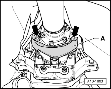
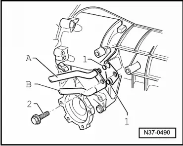
| Before installing gearbox, check for correct positioning of dowel sleeves -A- at cylinder block. Install new dowel sleeves if necessary. |
| –
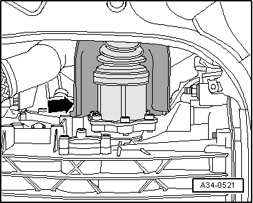
| If an intermediate plate was installed between engine and gearbox, reinstall plate in same position. |
| –
| When pushing the engine and gearbox together, ensure that no wiring or pipes etc. can become trapped. |

Caution | Before and while you are tightening the bolts on the engine/gearbox flange keep checking that the torque converter can still be rotated behind the drive plate. If the converter cannot be turned, it must be assumed that it has not been installed correctly and the drive lugs on the converter or the ATF pump will be damaged when the bolts are fully tightened. |
|
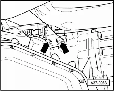
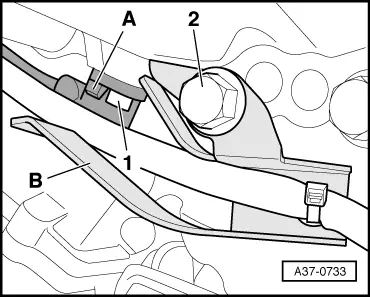
| –
| Use new ribbed bolts to secure the torque converter to the drive plate. Use only the correct bolts (same as original equipment) → Electronic parts catalogue. |
|
|
|

 Note
Note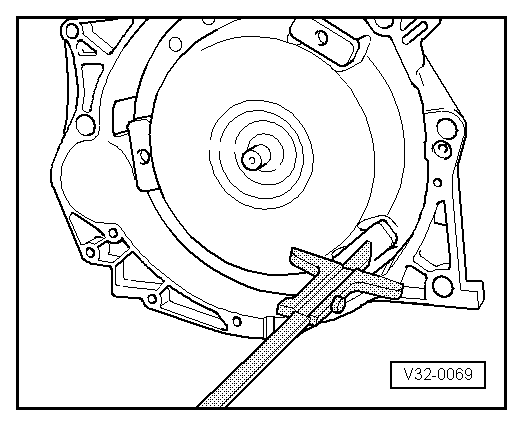
 WARNING