
A4 Cabriolet Mk2
| Removing gearbox on vehicles with 3.0 ltr. TDI engine |

| Special tools and workshop equipment required |
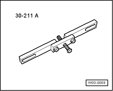
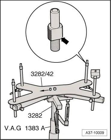
| t | Gearbox support -3282- |
| t | Adjustment plate -3282/48- |
| t | Pin -3282/50- |
| t | Engine and gearbox jack -V.A.G 1383 A- |
| t | Used oil collection and extraction unit -V.A.G 1782- |
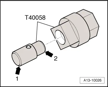
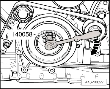
| t | Adapter -T40058- |
|
|
 Note
Note
|
|
 Caution
|
|
|
|
|
|
|
|
|
|
|
|
|

|
|
|
|
|
|
|
|
|
Note
Note |
|
|
|
Note |
|
Note
|
|
|
|
Note |
|
|
|
|
|
|
|
|
|
|
|
|
|
Note
|
|
|
|
Note
|
|
|
|
 WARNING
Note
|
|
Note
|
|
|
|
|
|
|
|
Note
|
|
|
|