
A4 Cabriolet Mk2
| Removing and installing camshaft adjuster |
| Special tools and workshop equipment required |
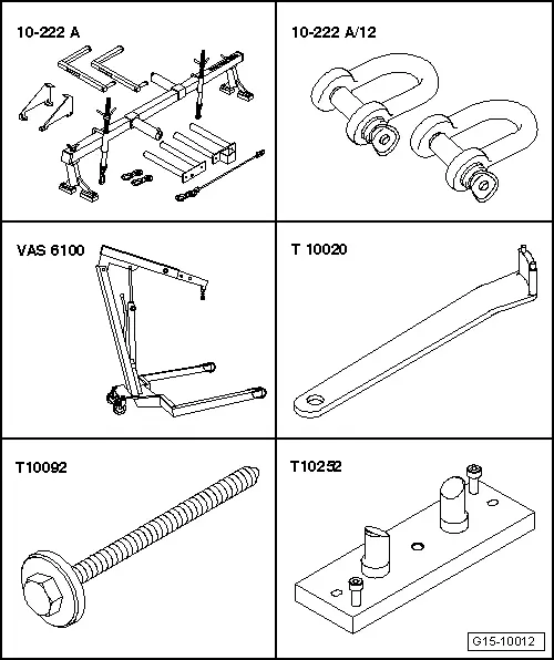
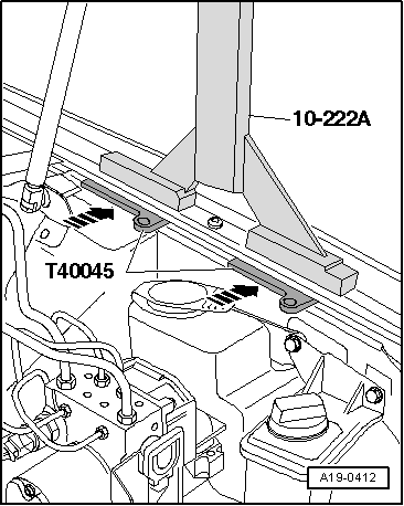
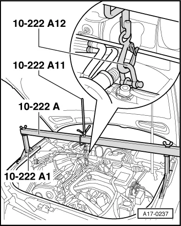
| t | Support bracket -10-222 A- |
| t | Shackle -10 -222 A /12- |
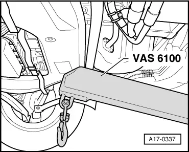
| t | Workshop hoist -VAS 6100- or -V.A.G 1202 A- |
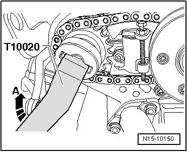
| t | Pin wrench -T10020- |
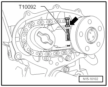
| t | Tensioning bolt -T10092- |
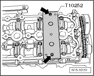
| t | Camshaft clamp -T10252- |
|
|
|
|
 Note
Note
|
|
 WARNING
|
|
|
|
|
|
|
|
|
|
|
|
|
|
|
|
|
|
Note |
|
|
|
|
|
|
|
Note
|
|
Note
|
|
|
|
Note
|
|
|
|
|
|
 Caution
|
|
Note
|
|
|
|
Note
|
|
|
|
Note
|
|
|
|
| Component | Nm | ||
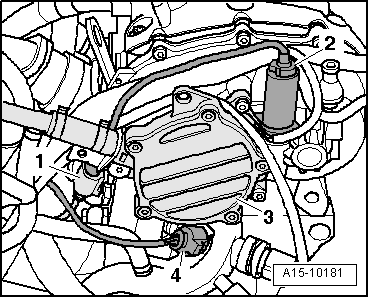
| Camshaft adjuster to camshaft | 100 | ||
| Chain tensioner to cylinder head | 10 1) | ||
| Camshaft adjuster cover to cylinder head | 10 1) | ||
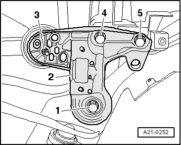
| Console for engine mounting to longitudinal member | 75 | ||
| Engine mounting to console for engine mounting | 23 | ||
| Torque reaction support to sump | 23 | ||
| |||