audi Workshop Repair Guides

Audi Workshop Service and Repair Manuals

Checking supporting elements with hydraulic clearance compensation > < Removing and installing camshaft adjuster
Renewing valve stem oil seals
   
Renewing valve stem oil seals
Special tools and workshop equipment required
t  Spark plug socket and extension -3122 B-
t  Valve stem seal puller -3364-
t  Valve stem seal fitting tool -3365-
t  Removal / installing device for valve cotters -VAS 5161- with guide plate for 2.0 ltr. FSI engine -VAS 5161/19-
t  Adapter -T40012-

Procedure
l  Cylinder head installed.
–  Remove camshafts → Chapter.
–  Remove roller rocker fingers and place onto a clean surface. When doing so, make sure that roller rocker fingers are not interchanged.
–  Remove spark plugs with spark plug socket -3122 B-.
   
–  Fit guide plate -VAS 5161/19- from removal / installing device for valve cotters -VAS 5161- on cylinder head.
–  Secure guide plate using the knurled screws -VAS 5161/12-.
–  Set piston of the respective cylinder to “bottom dead centre”.
  N15-10110
–  Screw adapter -T40012- into spark plug hole and connect to compressed air supply.
l  Minimum pressure: 6 bar.
–  Insert drift -VAS 5161/3- into guide plate and knock valve cotters loose using a plastic hammer.
  N15-10111
–  Screw snap-in device -VAS 5161/6- with engaging fork -VAS 5161/5- into guide plate.
–  Insert assembly cartridge -VAS 5161/8- into guide plate.
–  Attach pressure fork -VAS 5161/2- to snap-in device -VAS 5161/6- and push assembly cartridge down.
–  At the same time, turn knurled screw of assembly cartridge clockwise until tips engage in valve cotters.
–  Move knurled screw back and forth slightly; the valve cotters are thus forced apart and taken up by the assembly cartridge.
–  Release the pressure fork.
–  Remove assembly cartridge.
–  Detach guide plate and turn to one side.
l  The compressed air hose remains connected.
–  Remove valve spring with valve spring plate.
  N15-10112
–  Remove valve stem oil seals using the valve stem seal puller -3364-.
  Note
  A15-0559
t  
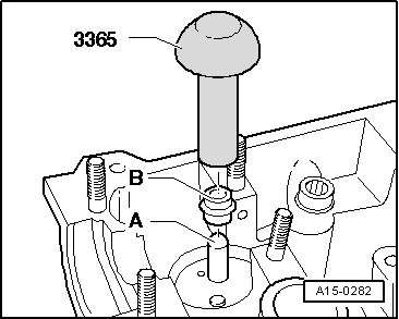
A plastic sleeve -A- is included with the new valve stem oil seals.
t  Sealing sleeves are fitted on the valve guides sleeves on certain engine versions.
t  If fitted, these sealing sleeves must not be removed → Item. Also, do not remove sealant in sleeves.
–  Fit plastic sleeve -A- onto the valve stem to prevent damage to the new valve stem oil seal -B-.
–  Lightly lubricate sealing lip of valve stem oil seal.
–  Slip valve stem oil seal over plastic sleeve.
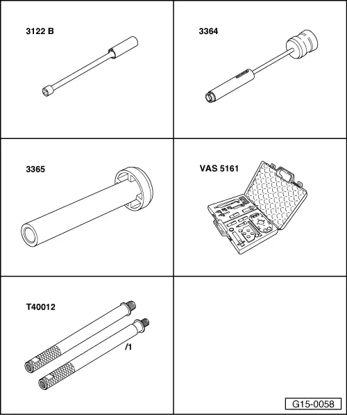
–  Carefully press valve stem oil seal onto valve guide using valve stem seal fitting tool -3365-.
–  Remove the plastic sleeve.
  A15-0282
If valve cotters have been removed from assembly cartridge, they need to be put into insertion device -VAS 5161/18- first.
l  Larger diameter of valve cotters faces upwards.
–  Press assembly cartridge -VAS 5161/8- onto insertion device from above and pick up valve cotters.
–  Install valve spring and valve spring plate.
  A15-0445
–  Screw guide plate back onto cylinder head.
–  Screw snap-in device -VAS 5161/6- with engaging fork -VAS 5161/5- into guide plate.
–  Re-insert assembly cartridge -VAS 5161/8- into guide plate.
–  Attach pressure fork -VAS 5161/2- to snap-in device -VAS 5161/6-.
–  Push pressure fork down and pull knurled screw upwards while turning to left and right - this will insert the valve cotters.
–  Release the pressure fork with knurled screw still in pulled position.
–  Detach guide plate -VAS 5161/19- from removal / installing device for valve cotters -VAS 5161- from cylinder head.
–  Ensure that all roller rocker fingers contact the ends of the valve stems correctly and are clipped onto their respective supporting elements.
–  Install camshafts → Anchor.
–  Install spark plugs → Rep. Gr.28.
  Note
t  After installing camshafts, wait for approx. 30 minutes before starting engine. Hydraulic valve compensation elements have to settle (otherwise valves will strike pistons).
t  After working on the valve gear, turn the engine carefully at least 2 rotations to ensure that none of the valves make contact when the starter is operated.
  N15-10112

Checking supporting elements with hydraulic clearance compensation > < Removing and installing camshaft adjuster