audi Workshop Repair Guides

Audi Workshop Service and Repair Manuals

Removing and installing sealing flange (front) > < Sealing flanges and dual-mass flywheel / flywheel - exploded view
Renewing crankshaft oil seal (pulley end)
   
Renewing crankshaft oil seal (pulley end)
Special tools and workshop equipment required
t  Oil seal extractor -3203-
t  Counterhold tool -3415-
t  Assembly tool -T10053-

Procedure
–  Move lock carrier to service position → Chapter.
–  Remove poly V-belt → Chapter.
–  Remove toothed belt → Chapter.
   
–  Remove crankshaft sprocket; use counterhold tool -3415- to lock sprocket in place.
  A13-0338
–  Before fitting oil seal extractor, fully screw in centre bolt for sprocket into crankshaft.
  A13-0067
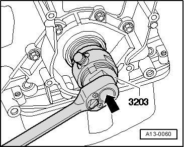
–  Unscrew inner section of oil seal extractor -3203- 8 turns out of outer section and lock with knurled screw.
–  Lubricate threaded head of oil seal extractor, place it in position and, exerting firm pressure -arrow-, screw it into oil seal as far as possible.
–  Loosen knurled screw and turn inner part against crankshaft until the oil seal is pulled out.
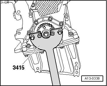
–  Clamp flats of oil seal extractor in vice.
–  Remove oil seal with pliers.
–  Clean running surface and sealing surface.
  Note
t  
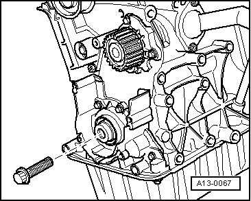
Renew the bolts tightened with specified tightening angle.
t  
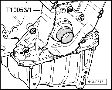
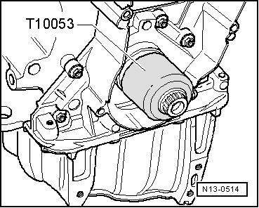
Do not lubricate sealing lip and outer rim of oil seal before pressing in.
  A13-0060
–  Place guide sleeve -T10053/1- onto crankshaft journal.
–  Slide oil seal over guide sleeve.
  N13-0513
–  Press in oil seal until flush using the centre bolt and assembly tool -T10053-.
  N13-0514
–  Renew centre bolt for toothed belt sprocket.
l  Contact surface between toothed belt sprocket and crankshaft must be free of oil.
l  Do not lubricate bolt for crankshaft sprocket.
–  Install crankshaft sprocket; use counterhold tool -3415- to lock sprocket in place.
Remaining installation steps are carried out in reverse sequence; note the following:
  Note
t  Hose connections and hoses for charge air system must be free of oil and grease before assembly. Do NOT use lubricant.
t  Secure all hose connections with the correct type of hose clips (same as original equipment) → Electronic parts catalogue.
t  To ensure that the charge air hoses can be properly secured at their connections, spray rust remover onto the worm thread of used hose clips before installing.
–  Install toothed belt (adjust valve timing) → Anchor.
–  Install vibration damper → Chapter.
–  Install poly V-belt → Chapter.
–  Install lock carrier with attachments → Rep. Gr.50.
  A13-0338
–  Allow stop for torque reaction support to rest on rubber buffer for torque reaction support under its own weight and tighten nuts -arrows-.
–  Install bumper cover (front) → Rep. Gr.63.
Tightening torques
  A10-10288
ComponentNm
Toothed belt sprocket to crankshaft120 + 90° 1)2)
Stop for torque reaction support to lock carrier28
Hose clips (9 mm wide)3
Hose clips (13 mm wide)5.5
l  1) Renew bolt.
l  2) 90° = one quarter turn.


Removing and installing sealing flange (front) > < Sealing flanges and dual-mass flywheel / flywheel - exploded view