
A4 Cabriolet Mk2
| Removing and installing sump (top section) |
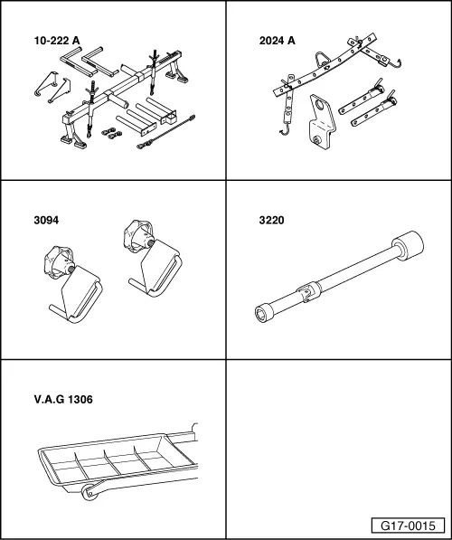
| Special tools and workshop equipment required |
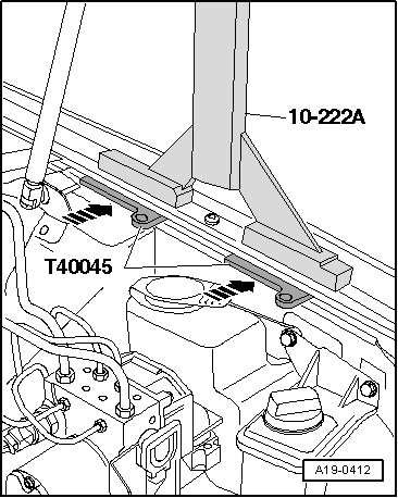
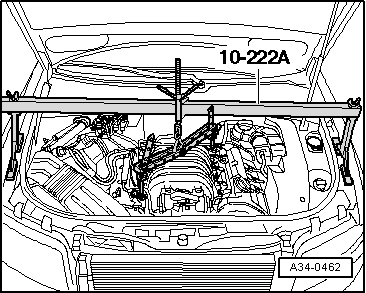
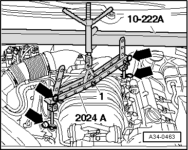
| t | Support bracket -10-222 A- |
| t | Lifting tackle -2024 A- |
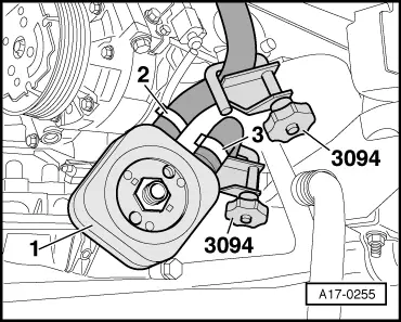
| t | Hose clamps for hoses up to 25 mm Ø -3094- |
| t | U/J extension and socket, 10 mm -3220- |
| t | Drip tray for workshop hoist -VAS 6208- or -V.A.G 1306- |
|
|
|
|
|
|
|
|
 Caution
|
|
|
|
|
|
|
|
 WARNING
|
|
|
|
 Note
Note |
|
|
|
Note
|
|
Note
|
|
|
|
|
|
Note
|
|
|
|
|
|
Note
|
|
|
|
Note
|
|
Note
|
|
|
|
Note
|
|
|
|
|
|
|
|
Note
|
|
|
|
|
|
Note
|
|
|
|
|
|
Note
|
|
|
|
| Component | Nm | |
| Sump (top section) to cylinder block and sealing flanges | M7 | 16 |
| M8 | 22 | |
| Sump (top section) to gearbox | 45 | |
| Bracket for noise insulation to subframe | 10 | |
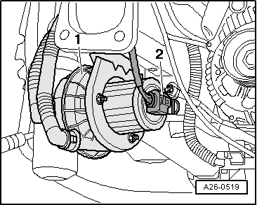
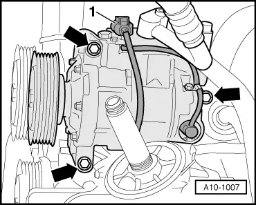
| Continued coolant circulation pump -V51- to sump (top section) | 10 | |
| Engine mounting to subframe | 23 | |
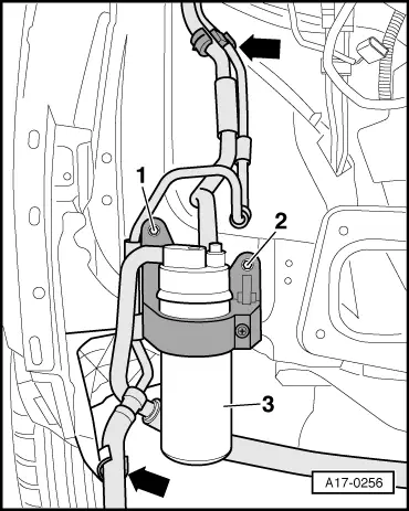
| Reservoir bracket to body | 10 | |
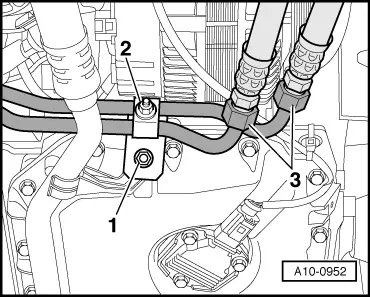
| Refrigerant line bracket to sump | 10 | |
| Secondary air pump bracket to longitudinal member | 10 | |
| Oil cooler to sump (top section) | 30 | |
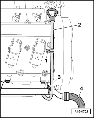
| Guide tube for oil dipstick to secondary air pipe | 10 | |