audi Workshop Repair Guides

Audi Workshop Service and Repair Manuals

Enginecrankshaft group, pistons > < Securing engine to engine and gearbox stand
Installing engine
Installing engine
  Note
t  Renew self-locking nuts and bolts when performing assembly work.
t  Renew bolts which are tightened to a specified angle as well as oil seals, gaskets and O-rings.
t  Secure all hose connections with the correct type of hose clips (same as original equipment) → Parts catalogue.
t  Fit all heat insulation sleeves in the original position when installing.
t  Fit all cable ties in the original positions when installing.
   
Checking installation position of torque converter
If the torque converter has been correctly installed, the distance between the contact surfaces at the threaded holes in the torque converter and the contact surface on the torque converter bell housing (with automatic gearbox 09L) is at least 19 mm.
  Caution
If the torque converter is not installed correctly, the drive lugs of the torque converter and the ATF pump will be seriously damaged when the gearbox is joined to the engine.
  A32-0011
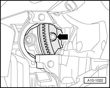
–  Before bringing engine and gearbox together, turn torque converter and drive plate on engine so that the holes for one securing bolt are in line with the opening for the starter motor -arrow-.
–  To secure torque converter on drive plate, use only new ribbed bolts of the correct type (same as original equipment) as specified in → Parts catalogue.
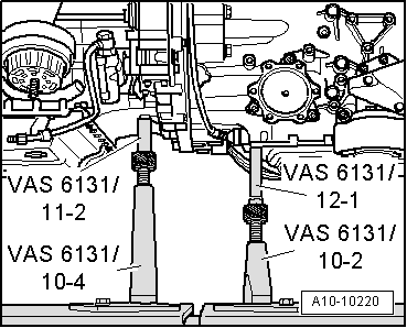
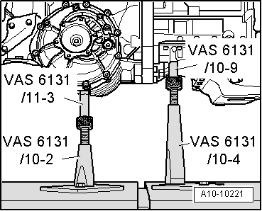
–  Bolt gearbox to engine.
  Caution
Before and during tightening of bolts on engine/gearbox flange, continually check that the torque converter behind the drive plate can be turned. If the converter cannot be turned, it must be assumed that it has not been installed correctly and the drive lugs of the ATF pump and consequently the gearbox will be damaged when the bolts are finally tightened.
  Note
t  Tightening torques apply only to lightly greased, oiled, phosphated or black-finished nuts and bolts.
t  Additional lubricant such as engine oil or gearbox oil may be used, but do not use lubricant containing graphite.
t  Do not use degreased parts.
t  Tolerance for tightening torques ± 15%.
  A10-1022
Securing engine to gearbox
  A37-0710
ItemBoltNm
1M12×8065
2, 4, 5M12×10565
3M12×11065
6M12×13065
7M12×17065
8, 9, 10M10x6045
ADowel sleeves for centralising

Remaining installation steps are carried out in reverse sequence; note the following:
–  Install front exhaust pipes together with catalytic converters: left-side → Chapter, right-side → Chapter.
–  Install ATF pipes → Rep. Gr.37.
–  The threaded holes in the flange shaft for the propshaft on the gearbox must be cleaned of remaining locking fluid with a thread tap before assembling.
   
–  Screw down the spindles for support elements (left-side) at engine/gearbox assembly.
–  Unscrew both base plates for support elements (left-side) at scissor-type assembly platform -VAS 6131 A-.
  A10-10220
–  Screw down the spindles for support elements (right-side) at engine/gearbox assembly.
–  Unscrew both base plates for support elements (right-side) at scissor-type assembly platform -VAS 6131 A-.
  Note
The mounting points for engine (front) and gearbox (rear) remain unchanged.
  A10-10221
–  Set up scissor-type assembly platform -VAS 6131 A- with support set for Audi -VAS 6131/10- as follows:
  A10-1764
Platform coordinatesParts of support set for Audi -VAS 6131/10-
B4 → Note/10-1/10-4/10-5/10-11
G3 → Note/10-1/10-4/10-5/10-11
B10/10-1/10-2/10-5/10-8 → Note
G10/10-1/10-2/10-5/10-8 → Note
C15 → Note/10-1/10-3/10-5/10-12
F15 → Note/10-1/10-3/10-5/10-12

1)  Support elements remain unchanged.
2)  Secure support elements only after installing the subframe.
   
–  Fit subframe onto the two support elements -VAS 6131/10-8-.
–  Screw up the spindles for support elements on both sides.
–  Tighten base plates for support elements to 20 Nm on scissor-type assembly platform -VAS 6131 A-.
–  Install left and right gearbox mountings → Rep. Gr.37.
–  Slowly guide engine gearbox assembly together with subframe into the body from below using scissor-type assembly platform -VAS 6131 A-.
  A10-10133
–  Adjust the subframe and consoles for engine mountings according to the markings made on the longitudinal members during removal.
–  Only tighten bolts for subframe and consoles for engine mountings to the specified torque (do not turn further); tighten bolts only after performing wheel alignment check.
1 - 65 Nm
2 - 110 Nm
3 - 110 Nm
4 - 75 Nm
  WARNING
The vehicle must not be driven at this stage.
Remaining installation steps are carried out in reverse sequence; note the following:
–  Install selector lever cable and check adjustment if necessary → Rep. Gr.37.
–  Install drive shafts → Rep. Gr.40.
–  Install guide links, track control links, anti-roll bar and suspension struts → Rep. Gr.40.
–  Align exhaust system so it is free of stress → Chapter.
–  Install refrigerant lines → Rep. Gr.87.
  A10-10219
USA vehicles:
–  Secure fuel hose at connection for fuel rail pipe. To do so, counterhold at hexagon flats -1- and -3- with open-end spanners and tighten union nut -2-: tightening torque 22 Nm.
All models:
–  Install lock carrier with attachments → Rep. Gr.50.
–  Install ATF pipes → Rep. Gr.37.
  A20-1202
–  Allow stop for torque reaction support to rest on rubber buffer for torque reaction support under its own weight and tighten bolts -arrows-.
–  Install bumper cover (front) → Rep. Gr.63.
–  Electrical connections and routing → Current flow diagrams, Electrical fault finding and Fitting locations.
–  Observe notes on procedures required after connecting battery → Rep. Gr.27.
  Caution
Do not use a battery charger to boost starting. There is danger of damaging the vehicle's control units.
–  Install and adjust wiper arms → Rep. Gr.92.
–  Check oil level → Chapter.
–  Before starting engine, top up hydraulic fluid in power steering reservoir → Rep. Gr.48.
  Note
The power steering pump must not be run when dry.
–  Fill cooling system → Anchor.
  Note
t  Drained-off coolant may only be used again if the original cylinder head and cylinder block are re-installed.
t  Contaminated or dirty coolant must not be used again.
–  Charge the refrigerant system → Air conditioner system - with refrigerant R134a.
–  Adjust subframe and the two consoles for engine mountings → Rep. Gr.40.
–  Perform wheel alignment check → Rep. Gr.44.
  WARNING
Tighten bolts for subframe to final setting after performing wheel alignment check.
–  Check headlight adjustment → Booklet803 or → Booklet805.
Tightening torques
  Note
t  Tightening torques apply only to lightly greased, oiled, phosphated or black-finished nuts and bolts.
t  Additional lubricant such as engine oil or gearbox oil may be used, but do not use lubricant containing graphite.
t  Do not use degreased parts.
t  Tolerance for tightening torques ± 15 %.
  A13-0633
ComponentNm
Bolts/nutsM69
 M820
 M1040
 M1265
Except for the following: 
Drive plate to torque converter85 → Note
Terminal B+ to starter16
Engine support to engine42 → Note
Drive shaft heat shield to gearbox23
Hydraulic pressure pipe40
Stop for torque reaction support to lock carrier28
Fuel hose to fuel line22

3)  Renew bolts.
4)  Apply locking fluid when fitting bolts.
   

Enginecrankshaft group, pistons > < Securing engine to engine and gearbox stand