audi Workshop Repair Guides

Audi Workshop Service and Repair Manuals

Removing and installing coolant pipe (left-side) > < Removing and installing coolant pipe (front)
Removing and installing coolant pipe (rear)
Special tools and workshop equipment required
   
t  Hose clip pliers -VAS 6340-
Removing
  Note
All cable ties which are released or cut open when removing must be fitted in the same position when installing.
–  Drain off coolant → Chapter.
–  Move lock carrier to service position → Chapter.
–  Remove coolant pipe (right-side) → Chapter.
–  Remove support bracket -10-222 A- from engine compartment.
  Note
The support bracket was necessary to remove the coolant pipe (right-side), however, it would be a hindrance for the remaining procedures.
  W00-10380
–  Detach coolant hoses -1- and -2-.
–  Unbolt coolant expansion tank -arrow-.
–  Unplug electrical connector for coolant shortage indicator switch -F66- at expansion tank (below).
  A10-1522
–  Remove electrical connectors -1 ... 4- from bracket (on left side of bulkhead).
–  Unbolt bracket from bulkhead.
  A24-0716
–  Detach vacuum line -arrow- going to brake servo at bulkhead.
  A10-1523
–  Disconnect coolant hose going to heat exchanger at coolant pipe (rear) on engine.
  A10-1459
–  Disconnect coolant hose from Y piece -arrow-.
  A10-1457
–  Unplug electrical connector -arrow- for Hall sender 2 -G163- at cylinder head (left-side).
  Note
In the following illustrations shown from rear with engine removed.
  A24-0556
–  Unplug electrical connector -arrow- for Hall sender -G40- at cylinder head (right-side).
  A24-0557
–  Unplug electrical connector -2- at coolant temperature sender -G2-/-G62-.
–  Unscrew nut -1- and detach electrical wiring harness at coolant pipe (rear).
  A19-0370
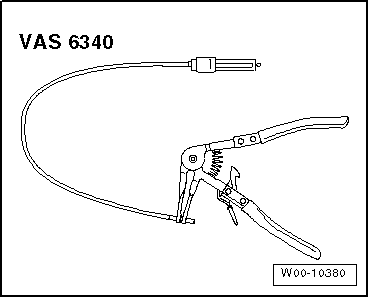
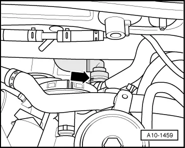
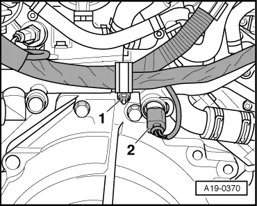
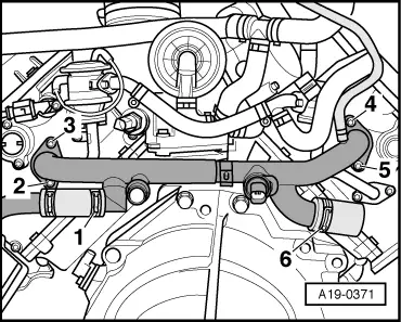
–  Release hose clip -1- using hose clip pliers -VAS 6340-.
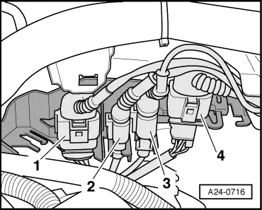
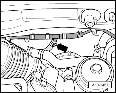
–  Release hose clip -6- using hose clip pliers -VAS 6340- and disconnect coolant hose.
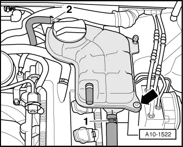
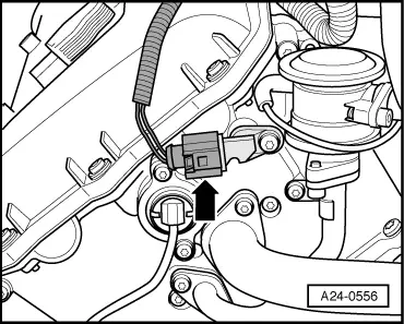
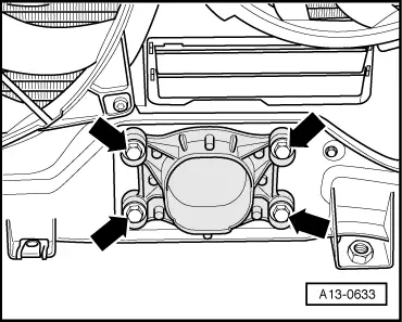
–  Remove bolts -2 ... 5-.
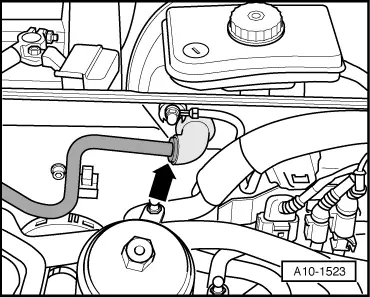
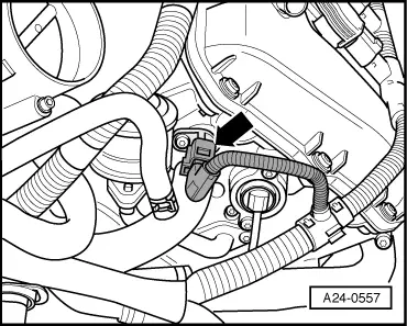
–  Detach coolant pipe (rear).
Installing
Installation is carried out in the reverse order; note the following:
  Note
t  Renew O-rings.
t  Secure all hose connections with the correct type of hose clips (same as original equipment) → Parts catalogue.
t  Fit all cable ties in the original positions when installing.
–  Before installing, clean and smooth down sealing surfaces for O-rings as required.
–  Coat new O-rings with acid-free grease (vaseline), fit coolant pipe (rear) and tighten.
–  Install coolant pipe (right-side) → Chapter.
–  Install lock carrier with attachments → Rep. Gr.50.
  A19-0371
–  Allow stop for torque reaction support to rest on rubber buffer for torque reaction support under its own weight and tighten bolts -arrows-.
–  Install bumper cover (front) → Rep. Gr.63.
–  Fill cooling system → Anchor.
–  Check headlight adjustment → Booklet803 or → Booklet805.
Tightening torques
  A13-0633
ComponentNm
Coolant pipe (rear) to cylinder head10
Clips to coolant pipe (rear)10


Removing and installing coolant pipe (left-side) > < Removing and installing coolant pipe (front)