
A4 Cabriolet Mk2

| Special tools and workshop equipment required |
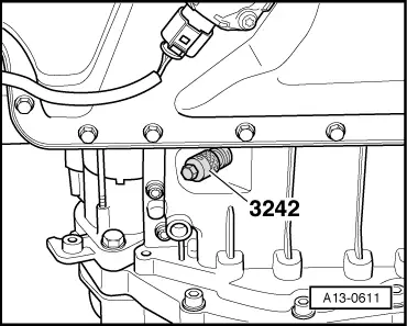
| t | Locking pin -3242- |
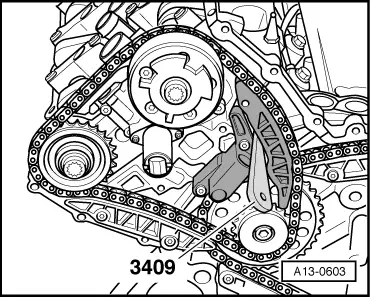
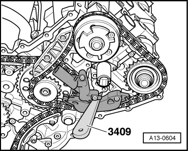
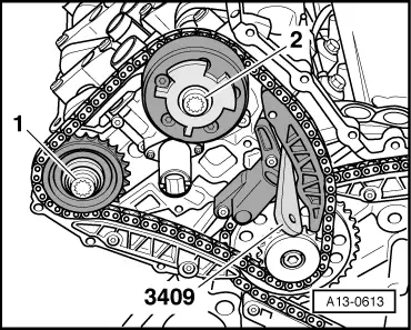
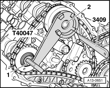
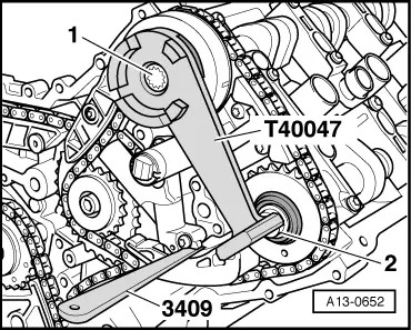
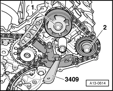
| t | Removal wedge -3409- (2x) |
| t | Used oil collection and extraction unit -V.A.G 1782- |
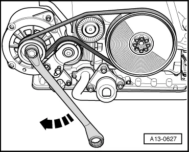
| t | Special wrench -T10035- |
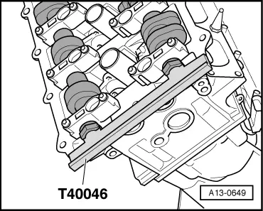
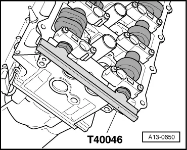
| t | Camshaft clamp -T40046- (2x) |
| t | Setting tool -T40047- |
 Note
Note
|
|
Note
|
|
|
|
|

|
Note
|
|
|
|
Note
|
|
Note
|
|
|
|
|
|
|
|
|
|
|
|
|
|
Note
|
|
|
|
|
|
|
|
|
|
|
|
Note
|
|
|
|
Note
|
|
|
|
|
|
|
|
|
|
|
|
|
|
|
|
|
|
|
|
|
|
Note
|
|
Note
|
|
|
|
Note
Note
|
|
|
|
|
|
|
|
|
|
|
|
|
|
|
|
|
|
|
|
|
|
Note
|
|
|
|
|
|
|
|
|
|
Note
|
|
|
|
|
|
|
|
|
|
|
|
|
|
|
|
|
|
|
|
|
|
|
|
| Component | Nm |
| Camshaft bolts | 100 + 90° → Note → Note |
| Screw plug in top section of sump | 35 |
| Oil drain plug | 50 |
|