audi Workshop Repair Guides

Audi Workshop Service and Repair Manuals

Checking fuel pressure and residual pressure (up to high-pressure pump) > < Injectors and fuel rail - exploded view
Removing and installing injectors
   
Removing and installing injectors
Special tools and workshop equipment required
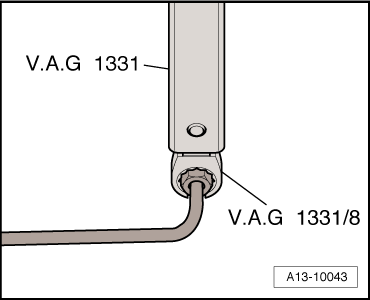
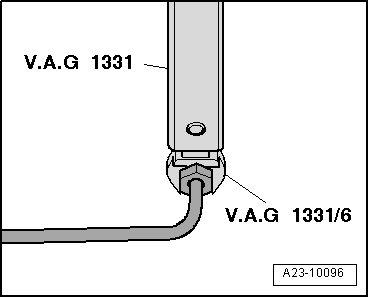
t  Torque wrench -V.A.G 1331-
t  Tool insert, AF 17 -V.A.G 1331/6-
t  Socket insert AF 14, flared ring spanner -V.A.G 1331/8-
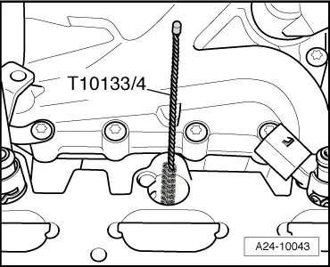
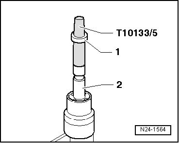
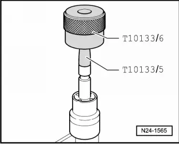
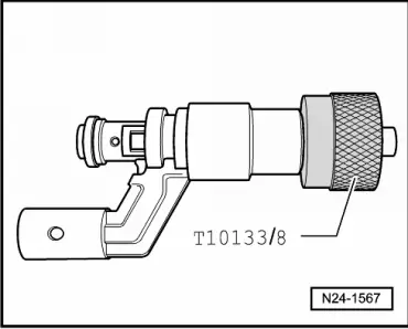
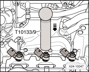
t  Tool set -T10133- with -T10133/10-

Removing
  WARNING
t  The fuel system operates under high pressure. The pressure in the high-pressure part of the injection system must be reduced to a residual pressure prior to opening the system → Chapter.
t  A clean cloth must then be wrapped around the connection and the residual pressure dissipated by carefully loosening the connection.
–  Drain off coolant → Rep. Gr.19.
–  Remove intake manifold → Chapter.
  Note
Seal off the injector openings in the cylinder heads with clean cloths.
   
–  Unplug electrical connectors at injectors.
–  Unscrew high-pressure pipe -5- at connection on fuel rail.
–  Unscrew high-pressure pipe -7- at connection on fuel rail. To do so, counterhold at hexagon flats with an open-end spanner and slacken union nut.
–  Remove bolts -1, 2, 3, 4, 6 and 8-.
  Note
Do not attempt to bend high-pressure pipes to a different shape.
–  Pull off fuel rail together with injectors.
  A24-10158
If injectors cannot be pulled out of cylinder head by hand, proceed as follows:
–  Use a screwdriver to bend retainer tabs -1- of radial compensation element to side -arrow- and pull support ring -2- off injector.
  A24-10041
–  Guide puller -T10133/2A- into groove on injector.
–  Then attach removal tool -T10133/16- and pull out injector by turning bolt -1-.
  Note
The combustion chamber ring seal must always be renewed before the injector is re-installed.
  A24-10579
–  Carefully remove old combustion chamber ring seal -arrow-. To do so, cut open ring using knife or prise open ring with small screwdriver and then pull off forwards.
–  Take care not to damage groove on injector. The injector must be renewed if the groove is damaged.
  N24-1563
Installing
  Note
t  Renew combustion chamber ring seal and O-ring.
t  Renew spacer ring if damaged.
t  Lightly lubricate O-rings for injectors with clean engine oil.
t  The injector pipes must be re-installed on the same cylinders.
–  Clean bore in cylinder head with nylon cylinder brush -T10133/4-.
  A24-10043
–  Clip radial compensation element -1- into support ring -2-.
–  When re-installing an injector, clean any combustion residue off groove for combustion chamber ring seal and injector stem with a clean cloth.
  A24-0590
–  Fit assembly cone -T10133/5- with new combustion chamber ring seal -1- onto injector -2-.
  N24-1564
–  Push combustion chamber ring seal onto assembly cone -T10133/5- as far as it will go using assembly sleeve -T10133/6-.
–  Turn assembly sleeve -T10133/6- upside down and push combustion chamber ring seal into groove.
  Note
  N24-1565
The combustion chamber ring seal is widened when it is pushed onto the injector. After pushing it on, it therefore has to be compressed again. This is done in two stages, as described below.
–  Push calibration sleeve -T10133/7- onto injector as far as it will go and simultaneously turn it slightly (approx. 180°).
–  Pull calibration sleeve -T10133/7- off again by turning it in the opposite direction.
  N24-1566
–  Push calibration sleeve -T10133/8- onto injector as far as it will go and simultaneously turn it slightly (approx. 180°).
–  Pull calibration sleeve -T10133/8- off again by turning it in the opposite direction.
–  Lubricate new O-ring lightly with clean engine oil before installing.
  Note
The combustion chamber ring seal must not be lubricated.
  N24-1567
–  Use assembly tool -T10133/9- to push injector as far as it will go into hole in cylinder head.
  Note
It should be possible to insert the injector easily. If necessary wait until the combustion chamber ring seal has contracted sufficiently.
–  Make sure injector is in correct installation position in cylinder head:
l  Electrical connector of injector must engage in recess in cylinder head.
–  Coat O-rings of injector with clean engine oil to facilitate insertion into fuel rail.
  A24-10047
–  Press fuel rail evenly onto injectors.
–  Tighten bolts -1, 2, 3, 4, 6 and 8- in diagonal sequence and in stages.
  Note
t  The connections of the high-pressure pipes must not be damaged.
  A24-10158
t  Do not attempt to bend high-pressure pipes to a different shape.
–  Tighten union nuts on high-pressure pipes hand-tight initially.
–  Ensure that high-pressure pipes are not under tension.
–  To tighten union nut (14 mm) for high-pressure pipe, use torque wrench -V.A.G 1331- with socket insert, 14 mm (flared ring spanner) -V.A.G 1331/8-.
  A13-10043
–  To tighten union nut (17 mm) for high-pressure pipe, use torque wrench -V.A.G 1331- with tool insert (17 mm) -V.A.G 1331/6-.
–  Do not install mounting brackets until high-pressure pipes have been finally secured.
Perform further installation in reverse order, paying attention to the following:
–  Install intake manifold → Chapter.
–  Fill cooling system → Rep. Gr.19.
  A23-10096

Checking fuel pressure and residual pressure (up to high-pressure pump) > < Injectors and fuel rail - exploded view