
A4 Mk1
|
Removing and installing gearbox
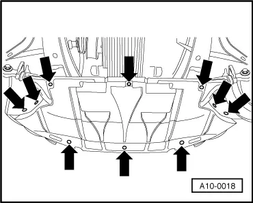
Removing
|
 |
|
|
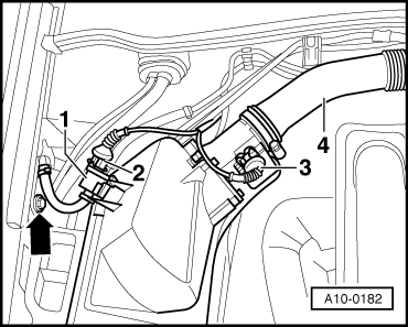
Vehicles with 4-cylinder normally aspirated engine:
=> 4 cylinder engine, Mechanics; Repair Group 26; Removing and installing parts of exhaust system Note: |
 |
|
|
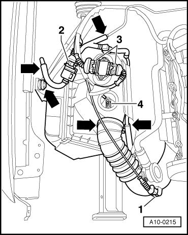
Avoid excessive bending of the flexible pipe connection (decoupling element) on the front exhaust pipe. The angle between the catalytic converter and the front exhaust pipe must not exceed 10o,otherwise the flexible connection will be damaged. Vehicles with 4 cylinder turbo engine:
|
 |
|
Note: Avoid excessive bending of the flexible pipe connection (decoupling element) on the front exhaust pipe. The angle between the catalytic converter and the front exhaust pipe must not exceed 10o, otherwise the flexible connection will be damaged. Vehicles with 6 cylinder engine: |
 |
|
All models:
|
 |
|
|
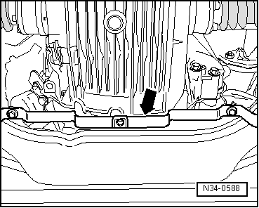 |
|
Vehicles with 4 cylinder engine: |
 |
|
|
 |
|
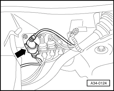
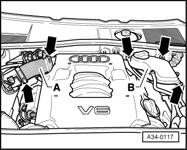
Vehicles with 6 cylinder engine:
|
 |
|
=> 6 cylinder Engine (2-valve), Mechanics; Repair Group 26; Removing and installing exhaust system |
 |
|
All models:
|
 |
|
|
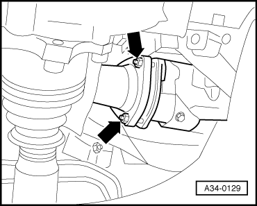
Note: Take care not to damage protective coating on drive shafts.
|
 |
|
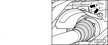
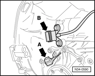
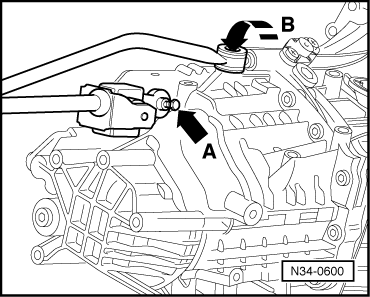
=> Electrical system; Repair Group 27; Removing and installing starter Note: Starter cables do not need to be disconnected. Vehicles with standard-travel shift mechanism: |
 |
|
Vehicles with short-travel shift mechanism: |
 |
|
All models: |
 |
|
|
 |
|
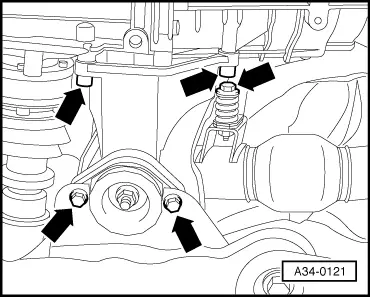
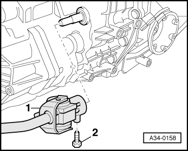
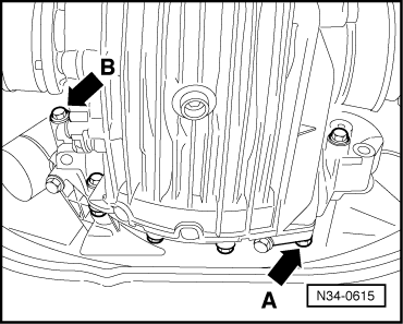
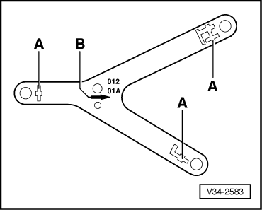
Notes:
|
 |
|
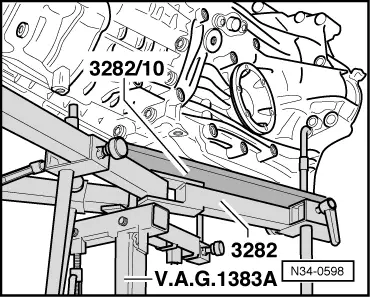
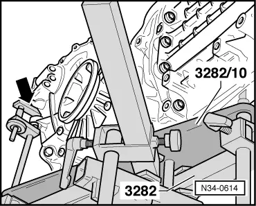
Note: If gearbox support 3282 is not available, gearbox can be removed and installed using gearbox lifter V.A.G 1383 A and universal support V.A.G 1359/2.
|
 |
|
Vehicles with 4 cylinder engine: |
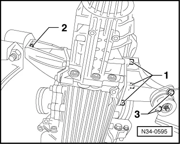 |
|
Vehicles with 6 cylinder engine: |
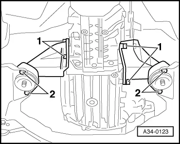 |
|
All models: |
 |
|
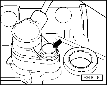
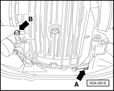
Note: When lowering gearbox ensure hydraulic pipe/hose to slave cylinder is not damaged. |
 |
|
Note: Do not depress clutch pedal after removing slave cylinder.
Note: When lowering gearbox ensure there is sufficient clearance to drive shafts. |