
A4 Mk1
 |
|
|
 |
|
|
 |
|
|
 |
|
|
 |
|
|
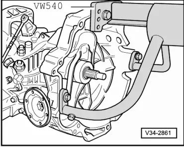
Dismantling
|
 |
|
|
 |
|
|
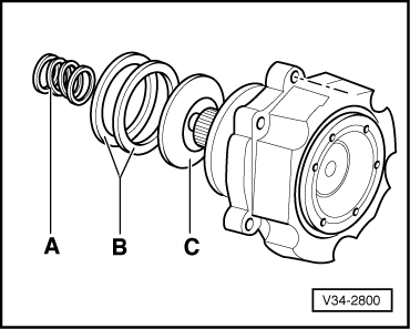
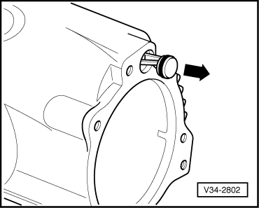
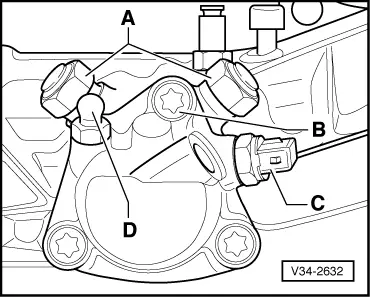
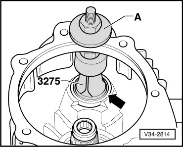
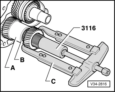
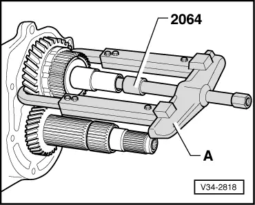
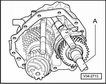
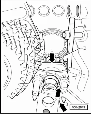
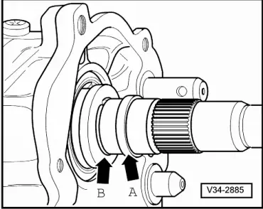
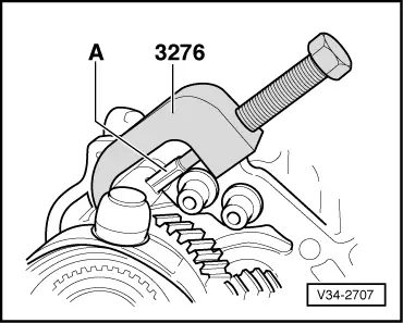
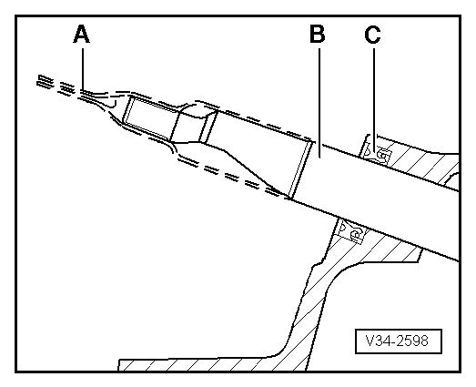
→ On detaching, bearing housing is pressed off end cover slightly by coil spring -A-.
|
 |
|
|
 |
|
 |
|
|
 |
|
 |
|
 |
|
 |
|
|
 |
|
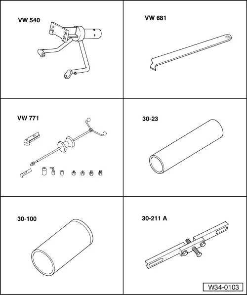
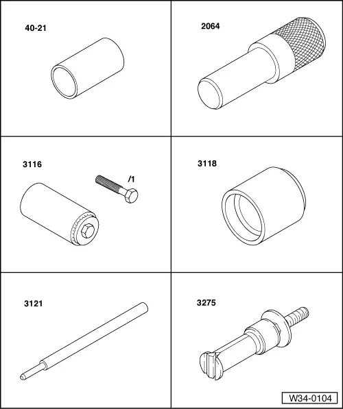
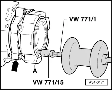
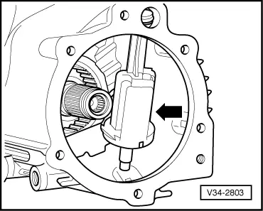
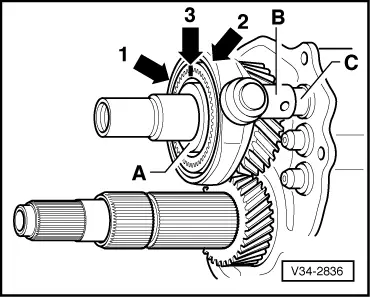
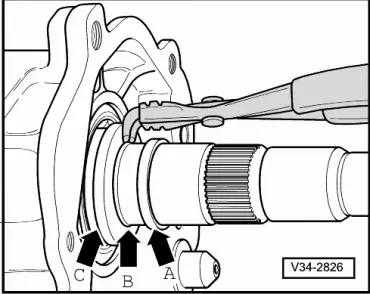
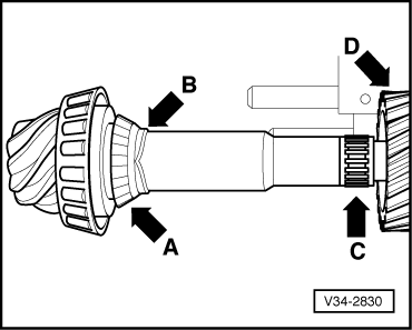
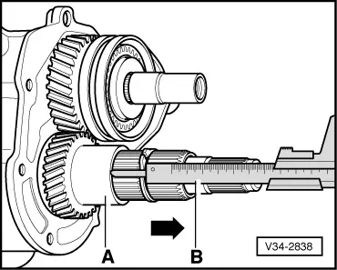
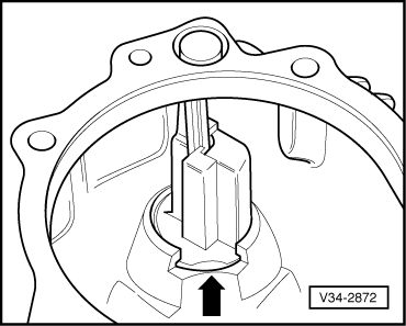
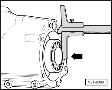
Note: On extraction, internal puller 3275 engages in all-round groove of inner race -arrow-.
|
 |
|
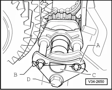
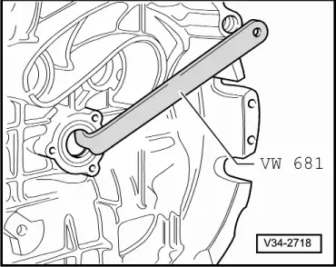
Note: Only use hexagon bolt of clamping sleeve 3116, length 50 mm.
|
 |
|
|
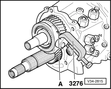
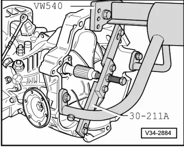
Note: Do not drive out spring pin as this could damage selector rod mount.
|
 |
|
 |
|
 |
|
|
 |
|
|
 |
|
 |
|
 |
|
|
 |
|
Notes:
|
 |
|
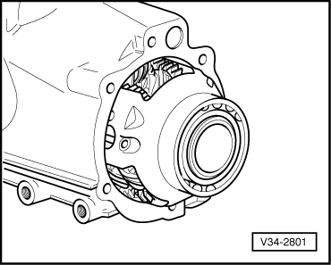
Note: Take care to avoid bearing contamination and clean if necessary. |
 |
|
|
 |
|
|
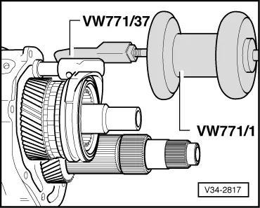
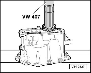
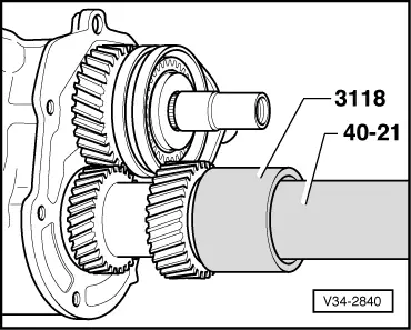
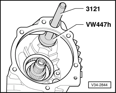
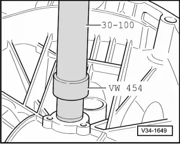
Note: Slight pressure may have to be exerted on account of type of fit.
|
 |
|
|
Assembly
Attention:
Wear protective gloves.
|
|
|
|
|
|
|
|
|
|
|
|
 |
|
|
|
|
 |
|
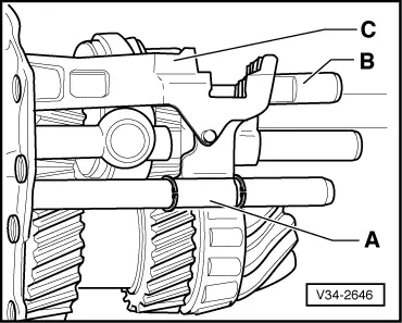
Note: On inserting complete bearing plate, make sure selector rods are aligned with bearing points.
|
|
|
|
 |
|
|
 |
|
|
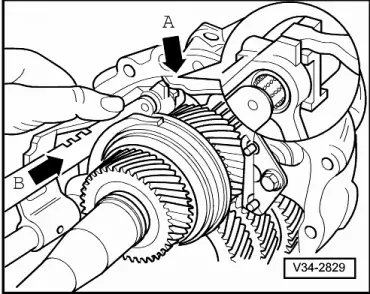
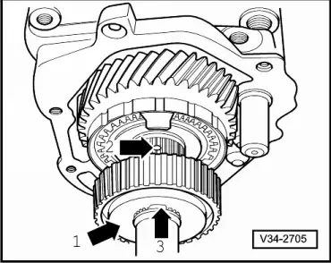
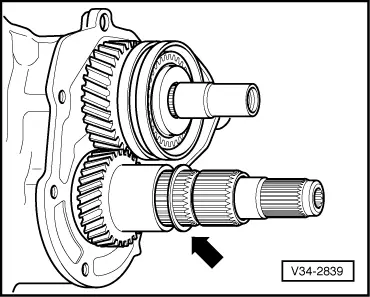
→ Installation position of synchro-hub for 5th and 6th gear:
|
 |
|
Attention:
Wear protective gloves. |
 |
|
|
Notes:
|
 |
|
|
 |
|
Attention:
Wear protective gloves. |
 |
||||||||||||||||
=> Parts List Circlips available:
| ||||||||||||||||
 |
|
 |
|
Attention:
Wear protective gloves. |
|
|
Note: Do not tighten bolts.
|
 |
|
|
|
 |
|
|
|
|
 |
|
|
 |
|
|
|
|
|
 |
||||||||||||||||||||||||||||||||||
=> Parts List Shims available:
|
|
|
|
 |
|
|