audi Workshop Repair Guides

Audi Workshop Service and Repair Manuals

Removing and installing selector lever handle > < Removing and installing shift mechanism with Tiptronic
Automatic Gearbox 01VFWD and 4WD
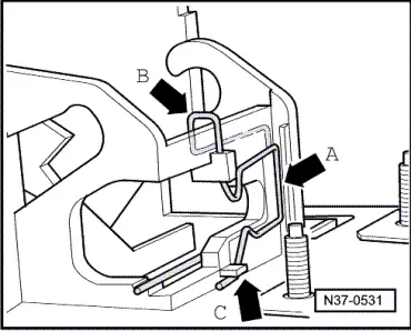
Servicing shift mechanism
Assembly overview of shift mechanism with Tiptronic
 
A37-0434

Assembly sequence

Lubricate mountings and sliding surfaces with polyurea grease, part number G 052 142 A2.

  • Handle for selector lever
    • ◆ Removing and installing
  • Sleeve
    • ◆ Engages in selector lever handle
  • Cover
    • ◆ Removing and installing
    • ◆ Dismantling and assembling => Page 37-26
 
A37-0434
  • Bush
    • ◆ Use securing clip -5- or -9- to secure in bearing cup -17-
    • ◆ Removing and installing
  • Securing clip (thin, with tensioning spring)
    • ◆ Secures bearing bush -4- in bearing cup -17-
    • ◆ Installation position:
      Angled ends point towards inside of bearing cup
  • Gate lever
    • ◆ With pull rod, compression spring, shift gate and Tiptronic springing
    • ◆ Removing and installing => from Page 37-22
    • ◆ Dismantling and assembling => Page 37-35
 
A37-0434
  • Spring
    • ◆ Removing and installing => from Page 37-35
  • Pull rod
    • ◆ Removing and installing => from Page 37-35
  • Securing clip (thick, without tensioning spring)
    • ◆ Secures bearing bush -4- in bearing cup -17-
    • ◆ Installation position:
      Angled ends point towards inside of bearing cup
  • Stop buffer
    • ◆ Clip into cable lever -12-
    • ◆ Installation position: Large contact surface facing selector lever
  • Latch plate
    • ◆ Clip into cable lever -12-
    • ◆ Removing and installing
 
A37-0434
  • Cable lever
    • ◆ Mounted with pivot pin -18- in bearing cup -17-
  • Detent spring with roller
    • ◆ For gearshift positions
    • ◆ Removing and installing => from Page 37-31
  • Detent spring with roller
    • ◆ For Tiptronic setting
    • ◆ Removing and installing => from Page 37-31
  • Frame
    • ◆ Clip or bolt onto bearing cup
    • ◆ Installation position: Ribs upwards
  • Nut, 10 Nm
  • Mount
    • ◆ Removing and installing => from Page 37-6
 
A37-0434
  • Pivot pin
    • ◆ Supports cable lever -12- in bearing cup -17-
  • Locking pawl
    • ◆ For selector lever lock
    • ◆ Removing and installing => from Page 37-31
  • Selector lever lock solenoid -N110-
    • ◆ Removing and installing => from Page 37-31
    • ◆ Can be checked in electrical test and in measured value block

=> Automatic Gearbox 01V, Self-diagnosis; Repair group 01; Performing self-diagnosis

 
A37-0434
  • Pivot pin
    • ◆ For locking pawl
    • ◆ Removing and installing => from Page 37-31
  • Cover
    • ◆ With gasket for bearing cup
    • ◆ Removing and installing => from Page 37-6
  • Nut, 10 Nm
  • Fixing
    • ◆ For selector lever cable on cable lever-12-
    • ◆ Fit angled end at front
  • Locking plate
    • ◆ For selector lever cable at bearing cup
    • ◆ Angled ends point towards inside of bearing cup
 
A37-0434
  • Selector lever cable
    • ◆ Do not bend or kink, lightly grease cable eye and ball socket before installing.
    • ◆ Removing and installing
    • ◆ Adjusting => Page 37-44
    • ◆ If the rubber sleeves are damaged the selector lever cable must be replaced
    • ◆ Do not twist rubber sleeve/gearbox side when installing
  • Hexagon bolt, 23 Nm
  • Support bracket
    • ◆ For selector lever cable to gearbox
    • ◆ Removing and installing
 
A37-0434
  • Cable tie
    • ◆ For locking cable
  • Ignition/starter switch
  • Locking cable
    • ◆ For ignition key removal lock
    • ◆ Must not be kinked
    • ◆ Removing and installing
    • ◆ Adjusting => Page 37-49
  • Locking lever
    • ◆ For ignition key removal lock
    • ◆ Removing and installing => from Page 37-31
 
A37-0434
  • Securing spring
    • ◆ For locking cable
    • ◆ Removing and installing => Fig.37-21
  • Mounting
    • ◆ for selector lever in Tiptronic setting
    • ◆ Removing and installing => from Page 37-31
 
N37-0531

Fig.1    Removing and installing securing spring for locking cable

Removing

  • ‒ → To remove locking cable, lift spring slightly at the top -arrow B-.
  • ‒ Disengage spring -arrow A- from retainer lug -arrow C- and lift out.

Installing

  • ‒ Insert spring from above -arrow B- and engage under retainer lug -arrow C-.
  • ‒ Align spring so that it lies level in groove -arrow A-.
  • ‒ To install interlock cable, lift spring slightly at the top -arrow B-.

Removing and installing selector lever handle > < Removing and installing shift mechanism with Tiptronic