
A4 Mk1
|
Removing and installing oil pan, ATF screen and valve body
Removing and installing valve body
Notes:
Removing |
 |
|
|
 |
|
|
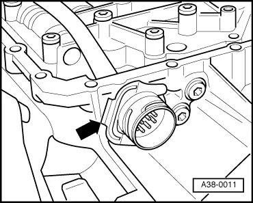
For gearbox with hydraulic control E17 only
|
 |
|
Notes:
|
 |
|
|
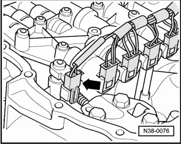
For gearbox with hydraulic control E18/2 only
|
|
|
Notes:
All models:
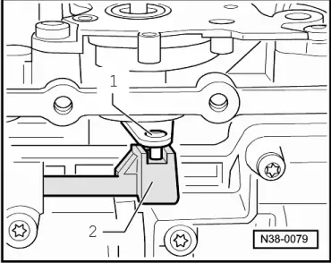
Note for gearbox with hydraulic control E17 only Do not stand the removed valve body on the gearbox input speed sender on the rear side of the valve body. This may cause damage. |
 |
|
|
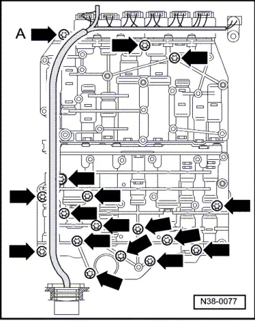
All models:
|
|
|
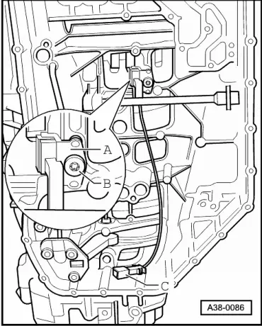
Notes: On gearboxes with hydraulic control E17 bolt -arrow A- is shorter/thinner than the other bolts. Note allocation Bolt -arrow A- is not fitted on gearboxes with hydraulic control E18/2 and can therefore be ignored here. |
 |
|
|
For gearbox with hydraulic control E18/2 only
|
|
|
|
For gearbox with hydraulic control E17 only
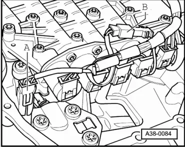
All models: |
|
|||||
Tightening torque
|