
A4 Mk1
|
|
|
|
|
|
|
|
|
|
|
|
|
|
|
|
|
|
|
|
|
|
|
|
|
|
|
|
|
|
|
|
|
|
|
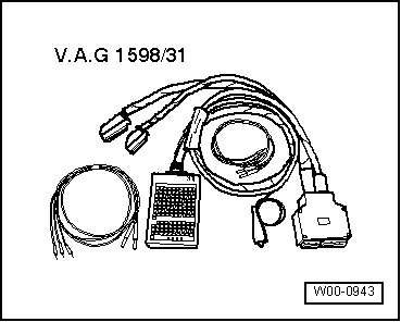
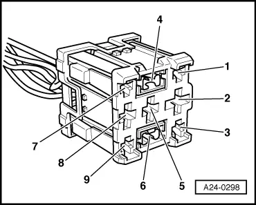
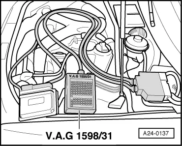
| Connector Contact | -V.A.G 1598/31- Socket |
| -6- | 66 |
|
|
|
|

|
|
|
|
|
|
|