audi Workshop Repair Guides

Audi Workshop Service and Repair Manuals

Check power supply relay for Motronic system -J271 > < Technical data
Motronic Fuel Injection and Ignition System (4-cyl) Turbo
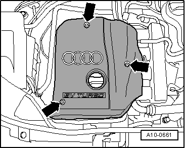
Checking ignition system
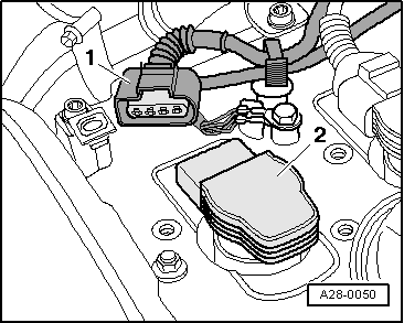
Check ignition coils with output stages
 
G24-0022

Special tools and workshop equipment required

  • ◆ V.A.G 1526 A
  • ◆ V.A.G 1527 B
  • ◆ V.A.G 1594 A
  • ◆ V.A.G 1598/31

Test sequence

Note:

The ignition coil and the output stage is combined in a common component.

 
A10-0661
  • ‒ → Remove engine cover -arrows-.

Identify an inoperative or misfiring cylinder as follows:

  • ‒ Check misfire detection .

If misfires are detected:

  • ‒ Continue checking the indicated cylinder => "If the defective cylinder has been detected".

If no misfires were detected:

  • ‒ Disconnect connectors from the injectors in sequence with the engine running, and observe how the engine runs.

or

  • ‒ Compare the spark plugs of all cylinders with each other and check for soot on the electrodes.

If the defective cylinder has been identified:

  • ‒ Replace the spark plug of the defective cylinder with one from another cylinder.

If the fault moves with the spark plug:

  • ‒ Renew the spark plug.

If the fault remains in the same cylinder:

  • ‒ Interchange the ignition coil from the defective cylinder with one from another cylinder.

If the fault moves with the ignition coil:

  • ‒ Replace the ignition coil.

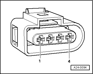
Test earth connection

 
A28-0050
  • ‒ → Unplug 4-pin connector -1- from ignition coil -2-.
 
A24-0094
  • ‒ → Connect voltage tester V.A.G 1527 B as follows:

Connector
contact

Measure to

2

Battery positive

4

Battery positive

    • ‒ The LED should light up.

If the LED does not light up:

  • ‒ Check the wiring connections.

=> Current Flow Diagrams, Electrical Fault-Finding and Fitting Locations

If the LED lights up:

  • ‒ Check the power supply.

Checking power supply

Test requirements:

  • ● Fuses for engine electronics OK

=> Current Flow Diagrams, Electrical Fault-Finding and Fitting Locations

 
A24-0094
  • ‒ → Connect multimeter as follows to measure voltage:

Connector
contact

Measure to

1

Engine earth

  • ‒ Switch the ignition on.
    • ‒ Specified value: approx. battery voltage

If specified value is attained:

  • ‒ Check actuation of output stages => Page 28-10.

If specified value is not attained:

 
A20-0564
  • ‒ → Remove rubber seal from plenum chamber cover in direction of arrow.
  • ‒ Remove plenum chamber cover -1- from the front.
 
A10-0761
  • ‒ → Remove cover for electronics box (plenum chamber) -arrows-.

 
A26-0357
  • ‒ → Pull off power supply relay -3-.
  • ‒ Carry out the following tests (marked with dots):
 
A24-0298
  • ● → Check the wiring of 3-pin relay carrier, position 2, contact 6 to connector of ignition coil contact 1.
  • ● Check power supply relay for Motronic -J271 => Page 28-13.

Checking actuation of power output stages

  • ‒ Unplug connectors from all injectors.

Note:

It is important to ensure that no fuel is injected during the test, as this would damage the catalytic converter. Therefore, the connectors on the injectors must be unplugged.

 
A28-0050
  • ‒ → Unplug 4-pin connector -1- from ignition coil -2-.

 
A24-0094
  • ‒ → Connect voltage tester V.A.G 1527 B to contacts 2 and 3 of the connector.
  • ‒ Operate starter briefly.
    • ‒ The diode test lamp should flash (very brief flash).

If specified values are not attained:

  • ‒ Connect the V.A.G 1598/31 test box to wiring harness leading to engine control unit; the engine control unit should not be connected => Page 24-19.
 
A24-0094
  • ‒ → Check for open circuit and short to positive or earth in the following wiring connections:

Connector
contact

Test box V.A.G 1598/31
Socket

3 (cyl. 1)

102

3 (cyl. 2)

95

3 (cyl. 3)

103

3 (cyl. 4)

94

  • ‒ Rectify any open/short circuit as necessary.

If no wiring fault is detected:

  • ‒ Replace the common component ignition coil with output stage.

Check power supply relay for Motronic system -J271 > < Technical data