-
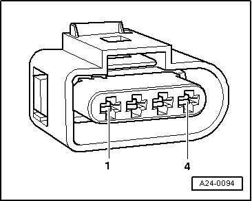
‒ → Connect multimeter as follows to measure voltage.
|
|
|---|
|
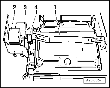
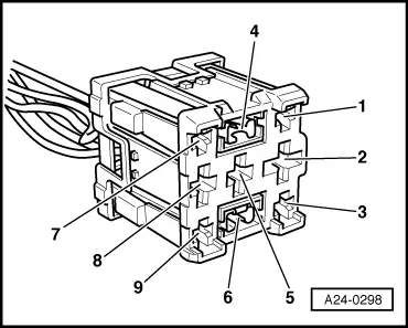
3-position relay carrier in E-box in plenum chamber, position 2
contact
|
Measure to
|
|
2
|
Engine earth
|
|
9
|
Engine earth
|
-
‒ Specified value: approx. battery voltage
If specified value is not attained:
-
‒ Carry out the following tests (marked with dots):
-
‒ Check the wiring between central electrics and power supply relay for open circuit.
=> Current Flow Diagrams, Electrical Fault-Finding and Fitting Locations
If no wiring fault is detected:
-
‒ Replace central electric's.
Checking actuation
|