audi Workshop Repair Guides

Audi Workshop Service and Repair Manuals

Checking engine speed sender -G28 > < Check power supply relay for Motronic system -J271
Motronic Fuel Injection and Ignition System (4-cyl) Turbo
Checking ignition system
Checking intake air temperature sensor -G42
 
G24-0021

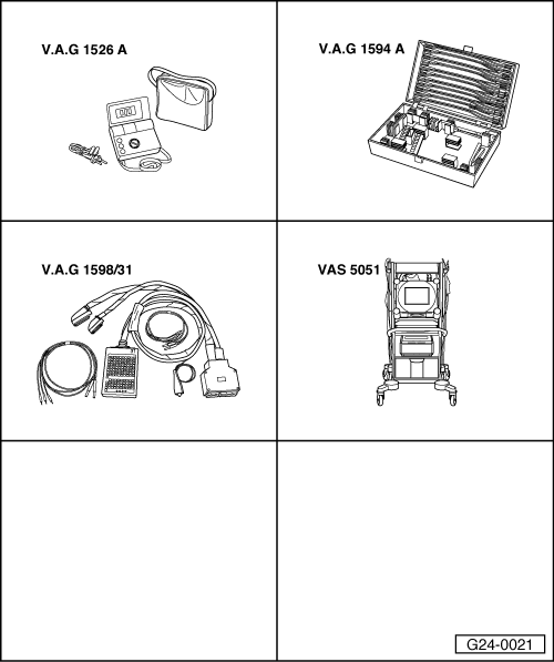
Special tools and workshop equipment required

  • ◆ V.A.G 1526 A
  • ◆ V.A.G 1594 A
  • ◆ V.A.G 1598/31
  • ◆ VAS 5051 with VAS 5051/1
  • or
  • ◆ V.A.G 1551 with V.A.G 1551/3 A

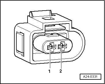
Fitting location => Fitting location overview Page 24-5

Test sequence

  • ‒ Connect the vehicle diagnostic, testing and information system VAS 5051 or fault reader V.A.G 1551 and select engine electronics control unit with "Address word" 01
    For this purpose, the engine must be running at idle speed
 
→ When indicated on display:
Rapid data transfer    HELP
Select function XX
  • ‒ Enter "08" to select the function "Reading measured value block" and confirm entry with Q key.
 
→ When indicated on display:
Reading measured value block    Q
Enter display group number XXX
  • ‒ Enter "004" for "display group number 004" and confirm entry with Q key.
 
→ Indicated on display:
Read measured value block 4    ⇒
    1    2    3    4
  • ‒ Check specified value for intake air temperature sender in display zone 4:

Display zones

1

2

3

4

Display group 004: Intake air temperature with engine idling

Display

xxxx rpm

xx.x V

xxx.x °C

xx.x °C

Display

Engine speed

Battery voltage

Coolant temperature

Intake air temperature

Range

-48.0...143.0 °C

Specified value

xxxx rpm

12.0....15.0 V:

80.0...110.0 °C

from ambient temperature up to 110 °C 1)

1)    If a temperature is displayed which deviates greatly from the ambient temperature of the sender, check sender and sender wiring for contact resistances and open circuit.

Checking wiring

 
A28-0051
  • ‒ Connect the V.A.G 1598/31 test box to wiring harness leading to engine control unit; the engine control unit should not be connected => Page 24-19.
  • ‒ → Unplug connector -1- at coolant temperature sender -G42 -2-.

 
A24-0331
  • ‒ → Check for open circuit and short to positive or earth in the following wiring connections:

Connector
contact

Test box V.A.G 1598/31
Socket

1

85

2

108

  • ‒ Test for short circuits between the two wires.
  • ‒ Rectify any open/short circuit as necessary.

If no wiring fault is detected:

Checking sender:
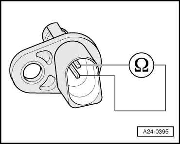
 
A24-0395
  • ‒ → Connect multimeter to sender to measure resistance.

Specifications:

Temperature °C

Resistance kω

-20

approx. 13.8

0

approx. 5.5

20

approx. 2.4

40

approx. 1.1

60

approx. 0.6

If specified value is not attained:

  • ‒ Replace intake air temperature sender.

Checking engine speed sender -G28 > < Check power supply relay for Motronic system -J271