audi Workshop Repair Guides

Audi Workshop Service and Repair Manuals

Testing fuel pump relay -J17 and activation > < Removing and installing injectors
Motronic injection and ignition system (4-cyl. turbo)
Servicing Motronic injection system
Checking injection quantity, leak-tightness and spray pattern of injectors
 
G24-0025

Special tools and workshop equipment required

  • ◆ V.A.G 1348/3A
  • ◆ V.A.G 1594 A
  • ◆ V.A.G 1598/31
  • ◆ V.A.G 1602
  • ◆ VAS 5051 with VAS 5051/1

or

  • ◆ V.A.G 1551 with V.A.G 1551/3 A

Test requirement:

  • ● Fuel pressure OK. Testing .

Test sequence

  • ‒ Remove fuel rail (together with injectors) from intake manifold => Page 24-45. Do not disconnect the fuel hoses.
  • ‒ Connect test box V.A.G 1598/31 to wiring harness for engine control unit. Do not connect to the engine control unit itself.
    => Page 24-20.

Testing for leaks

  • ‒ Bridge contacts 1 and 65 on the test box using test leads from adapter set V.A.G 1594 A.

Only on vehicles from model year 2001 onwards with engine code ANB:

  • ‒ Switch on ignition.

All models

    • ‒ The fuel pump should run.
  • Check injectors for leaks (visual check). When the fuel pump is running, only 1 or 2 drops should escape per minute from each injector.
  • ‒ If a greater amount of fuel escapes, switch off the fuel pump (disconnect the cable bridge) and replace the faulty injector => Page 24-45.
 
A24-0079

Checking injection quantity

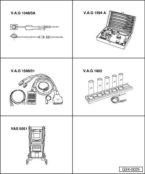
  • ‒ Place the injector which is to be tested into a measuring glass from injection quantity tester V.A.G 1602.
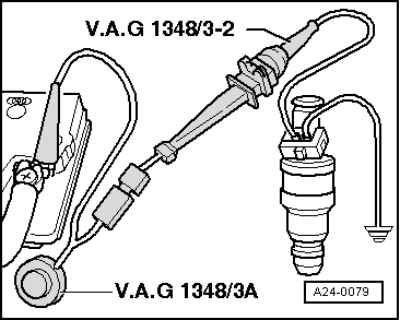
  • ‒ → Connect one of the injector contacts to engine earth using test lead and crocodile clamp from V.A.G 1594 A.
  • ‒ Connect second injector contact to positive using remote control V.A.G 1348/3 A, adapter cable V.A.G 1348/3-2 and auxiliary cable.
  • ‒ Bridge contacts 1 and 65 on the test box using test leads from adapter set V.A.G 1594 A.

Only on vehicles from model year 2001 onwards with engine code ANB:

  • ‒ Switch on ignition.

All models

    • ‒ The fuel pump should run.
  • ‒ Activate remote control V.A.G 1348/3A for 30 seconds.
  • ‒ Carry out measurement on all injectors.
  • ‒ Once all four injectors have been actuated, place measuring glasses on a level surface.
    • ‒ Specification for each injector: 135 ±10 ml

Note:

Export models for Brazil=> Page24-4.

  • ‒ If the measured value for one or more of the injectors is outside the tolerance range, switch off the fuel pump (by disconnecting the cable bridge) and replace the defective injector => Page 24-45.

Note:

When checking the injection quantity, also check the spray pattern. The spray pattern should be the same for all the injectors.

  • ‒ Install injectors together with fuel rail => Page 24-46.

Testing fuel pump relay -J17 and activation > < Removing and installing injectors