audi Workshop Repair Guides

Audi Workshop Service and Repair Manuals

Testing air mass meter -G70 > < Checking injection quantity, leak-tightness and spray pattern of injectors
Motronic injection and ignition system (4-cyl. turbo)
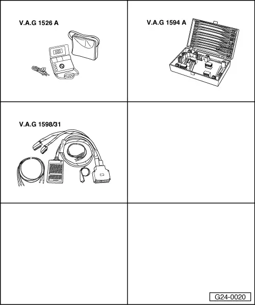
Servicing Motronic injection system
Testing fuel pump relay -J17 and activation
 
G24-0020

Special tools and workshop equipment required

  • ◆ V.A.G 1526 A
  • ◆ V.A.G 1594 A
  • ◆ V.A.G 1598/31

The fuel pump and some of the injection system components receive their voltage supply via fuel pump relay -J17.

Fuel pump relay -J17 will only close if the engine is turning over. In other words, the relay is only earthed (via the engine control unit) when the engine control unit is receiving engine revolution impulses.

 
A97-0110

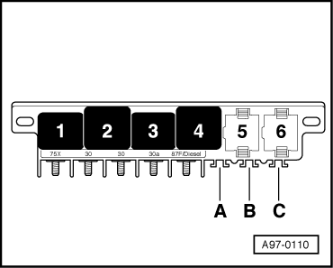
Note:

→ The fuel pump relay is located in the central electrics on the left of the driver's footwell, relay position 4.

Test requirement:

  • ● Battery voltage not less than 12.7 V

Testing operation of fuel pump relay

  • ‒ Remove storage compartment on driver's side.

=> General body repairs, Interior; Repair group 68; Storage compartments, covers and trim parts; Removing and installing driver's storage compartment

  • ‒ Connect vehicle diagnostic, testing and information system VAS 5051 (or fault reader V.A.G 1551) and select engine electronics control unit by entering address word "01" ( .)
    When doing this the ignition must be switched on.
  • ‒ Start final control diagnosis (=> Page 01-37) and activate ACF solenoid valve 1 (-N80).
 
A97-0110
    • ‒ → The fuel pump relay should pick up and the fuel pump should run. (Relay is located in relay position 4 in central electrics on left of driver's footwell).

A - If the relay does not pick up:

  • ‒ Test voltage supply to fuel pump relay => Page 24-53.
  • ‒ Test activation of fuel pump relay => Page 24-53.

B - If the relay picks up but the fuel pump does not run:

  • ‒ Test voltage supply to fuel pump and other components (via fuel pump relay) .
 
A24-0100

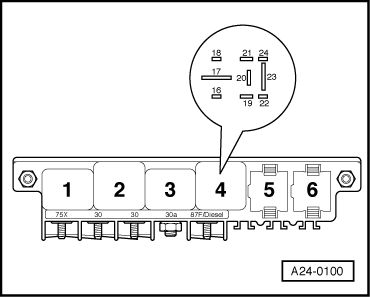
Testing voltage supply to fuel pump relay

  • ‒ → Connect multimeter (voltage measurement range) to earth and contact 17 on relay panel.
    • ‒ Specification: approx. battery voltage

If the specification is not obtained:

  • ‒ Replace central electrics unit

Testing activation of fuel pump relay

  • ‒ Switch off ignition.
  • ‒ Connect test box V.A.G 1598/31 to wiring harness for engine control unit. Do not connect to the engine control unit itself.
    => Page 24-20.
  • ‒ Bridge contacts 1 and 65 on the test box using test leads from adapter set V.A.G 1594 A.

Only on vehicles from model year 2001 onwards with engine code ANB:

  • ‒ Switch on ignition.
 
A97-0110

All models

    • ‒ → The fuel pump relay should pick up. (Relay is located in relay position 4 in central electrics on left of driver's footwell).

If the relay picks up now but not during the final control diagnosis:

  • ‒ Fit a new engine control unit => Page 24-24.

If the relay does not pick up:

  • ‒ Switch off ignition.
  • ‒ Disconnect cable bridge.
  • ‒ Disconnect fuel pump relay.
 
A24-0100
  • ‒ → Connect multimeter (voltage measurement range) between earth and contact 19 on relay panel.
    • ‒ Specification: approx. battery voltage

If the specification is not obtained:

  • ‒ Check the wiring.

=> Current flow diagrams, Electrical fault finding and Fitting locations binder

 
A24-0100

If the specification is obtained:

  • ‒ → Test for open circuit and short to positive or earth in the following wiring connections:

Central electrics on left of driver's footwell, relay position 4
Contact

Test box V.A.G 1598/31


Socket

16

65

  • ‒ Rectify any open/short circuit as necessary.

If no fault is found:

  • ‒ Fit a new fuel pump relay -J17.
  • ‒ Reconnect the engine control unit.
 
A97-0119

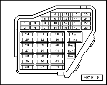
Testing voltage supply to fuel pump and other components

  • ‒ → Remove fuse Nos.S228, S2291), S2322) and S234 from fuse holder(at socket positions 28, 32 and 34).

    1)    only on vehicles up to model year 1999

    2)    only on vehicles from model year 2000 onwards

  • ‒ Start final control diagnosis (=> Page 01-37) and activate ACF solenoid valve 1 (-N80).
  • ‒ For each of the following fuse positions in the fuse holder, connect the multimeter (voltage measurement range) between earth and one of the fuse contacts:

Fuse

Specification
(for one contact)

S228

Approx. battery voltage

S229 1)

Approx. battery voltage

S232 2)

Approx. battery voltage

S234

Approx. battery voltage

    1)    only on vehicles up to model year 1999

    2)    only on vehicles from model year 2000 onwards

If the specifications are not obtained:

  • ‒ Repeat the test on the other fuse contact.

If the specifications are again not attained:

  • ‒ Check wiring

=> Current flow diagrams, Electrical fault finding and Fitting locations binder

If no fault is found:

  • ‒ Fit a new fuel pump relay -J17.
  • ‒ Refit fuses.

Testing air mass meter -G70 > < Checking injection quantity, leak-tightness and spray pattern of injectors