audi Workshop Repair Guides

Audi Workshop Service and Repair Manuals

Testing camshaft timing control > < Testing knock sensors
Motronic injection and ignition system (6-cylinder)
Testing ignition system
Checking Hall sender

Notes:

  • ◆ Hall sender -G40 is located at the rear of the left-hand cylinder head (Bank 2).
  • ◆ Hall sender -G163 is located at the front of the right-hand cylinder head (Bank 1).
  • ◆ Fitting location.

Special tools, testers and auxiliary items

  • ◆ Hand multimeter V.A.G 1526 or V.A.G 1526 A
  • ◆ Diode test lamp V.A.G 1527
  • ◆ Adapter set V.A.G 1594
  • ◆ Test box V.A.G 1598/22
 
V96-0836

Testing voltage supply

  • ‒ Unplug 3-pin connector from the Hall sender which is to be tested.
  • ‒ → Connect hand-held multimeter V.A.G 1526 to contacts 1 (positive) and 3 (earth) of the connector.
  • ‒ Switch ignition on.
    • ‒ Specification: at least 9 V
  • ‒ If the value does not match the specification, test for open circuits and short circuits in wiring between Hall senders and engine control unit using current flow diagram.

=> Current flow diagrams, Electrical fault-finding and Fitting locations

  • ‒ Connect test box V.A.G 1598/22 to the wiring harness for the engine control unit.
 
V96-0836
  • ‒ → Test for open circuit in earth wire between contact 3 on connector for Hall sender -G40 and socket 67 on test box.
    • ‒ Specification: max. 1ω
  • ‒ Test for open circuit in positive wire between contact 1 on connector for Hall sender -G40 and socket 11 on test box.
    • ‒ Specification: max. 1ω
  • ‒ Test for short circuits between the two wires.
  • ‒ Test for open circuit in earth wire between contact 3 on connector for Hall sender -G163 and socket 14 on test box.
    • ‒ Specification: max. 1ω
  • ‒ Test for open circuit in positive wire between contact 1 on connector for Hall sender -G163 and socket 11 on test box.
    • ‒ Specification: max. 1ω
  • ‒ Test for short circuits between the two wires.
 
A28-0022
  • ‒ → If one of the values does not match the specification, test for open circuit or short circuit between sender connectors and engine control unit connectors.
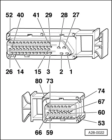
Connector for
Hall sender -G40

Contact on control unit connector

1 (positive)

11

3 (earth)

67

Connector for
Hall sender -G163

Contact on control unit connector

1 (positive)

11

3 (earth)

14

  • ‒ If there are no open circuits or short circuits, fit a new engine control unit => Page 24-26.

Testing operation

Note:

To test the operation of the Hall senders, unplug the 5-pin connector from the output stage together with the ignition coils (interrogate fault memory after testing).

Test conditions

  • ● Voltage supply to Hall senders OK
    Testing => Page 28-31.
  • ‒ Slide back rubber sleeves on connectors for Hall senders but leave connectors plugged in.
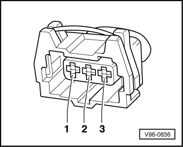
  • ‒ Connect diode test lamp V.A.G 1527 between contact 2 (Hall sender signal) and contact 1 (positive) on each connector in turn.

Note:

The connector contacts are numbered on the back of the connector.

  • ‒ Operate starter for a few seconds.

The diode test lamp should flash briefly on alternate engine revolutions (i.e. once every two revolutions).

  • ‒ If the diode test lamp does not flash, switch off ignition and unplug 3-pin connector on Hall sender.
  • ‒ Connect test box V.A.G 1598/22 to the wiring harness for the engine control unit.
    => Page 24-24
  • ‒ Test for open circuit in signal wire between contact 2 on connector for Hall sender -G40 and socket 76 on test box.
  • ‒ Test for open circuit in signal wire between contact 2 on connector for Hall sender -G163 and socket 44 on test box.
    • ‒ Specification: max. 1ω
 
V96-0836
  • ‒ → If the value does not match the specification, rectify short circuit or open circuit in wiring between Hall sender connector...
 
A28-0022
  • ‒ → ...and control unit connector.

Contact on connector for Hall sender -G40

Contact on control unit connector

2 (signal)

76

Contact on connector for Hall sender -G163

Contact on control unit connector

2 (signal)

44

  • ‒ If there are no open circuits or short circuits, reconnect engine control unit to engine wiring harness.
  • ‒ Connect hand-held multimeter V.A.G 1526 between contacts 2 and 3 of each Hall sender connector in turn.
  • ‒ Switch ignition on.
    • ‒ Specification: at least 9 V
  • ‒ If the values do not match the specification, fit a new engine control unit => Page 24-26.
  • ‒ If the values match the specifications, fit a new Hall sender.

Testing camshaft timing control > < Testing knock sensors