audi Workshop Repair Guides

Audi Workshop Service and Repair Manuals

Checking Hall sender > < Checking control unit voltage supply
Motronic injection and ignition system (6-cylinder)
Testing ignition system
Testing knock sensors

Notes:

  • ◆ To test the operation of the knock sensors, use the function "Read measured value block", Display Groups 012, 013, 014 and 015.
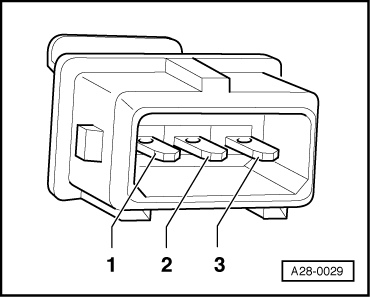
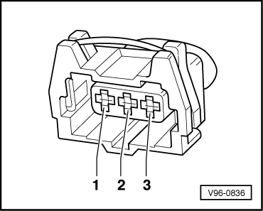
  • ◆ Fitting locations of plug connectors and knock sensors
    .
  • ◆ It is not possible to carry out an electrical test of the knock sensors themselves. See "Interrogating fault memory", Page 01-7.
  • ◆ In order to remove and install the knock sensors the intake manifold must be removed.
  • ◆ To ensure that the knock sensors function properly it is important to keep exactly to the specified tightening torque of 20 Nm.
  • ◆ Check connectors for corrosion.
  • ◆ Use only gold-plated contacts when repairing the contacts in the plug connectors for the knock sensors.

Special tools, testers and auxiliary items

  • ◆ Hand multimeter V.A.G 1526 or V.A.G 1526 A
  • ◆ Adapter set V.A.G 1594
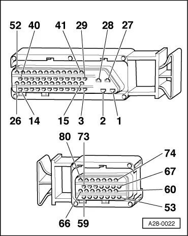
  • ◆ Test box V.A.G 1598/22

Testing knock sensor wiring

  • ‒ Unplug the connector for the relevant knock sensor in the engine compartment.
 
A28-0029
  • ‒ → Test for short circuits between all three contacts in the knock sensor connector. The must be no connection between any of the wires.
  • ‒ If there is a connection between the contacts, fit a new knock sensor.

Testing wiring from knock sensors to engine control unit

  • ‒ Connect test box V.A.G 1598/22 to wiring harness for engine control unit
    => Page 24-24.
  • ‒ Using the current flow diagram, test for continuity and short circuits in the wiring between the sender and engine control unit.

=> Current flow diagrams, Electrical fault-finding and Fitting locations

 
V96-0836
  • → Identification of contacts in plug connector:

Signal wire

Earth wire

Screening

1

2

3

  • ‒ Test continuity of signal wire of knock sensor 1 (-G61) from contact 1 on connector in engine compartment to socket 68 on test box.
    • ‒ Specification: max. 1ω
  • ‒ Test continuity of earth wire of knock sensor 1 (-G61) from contact 2 on connector in engine compartment to socket 67 on test box.
    • ‒ Specification: max. 1ω
  • ‒ Test continuity of screening on wiring for knock sensor 1 (-G61) from contact 3 on connector in engine compartment to socket 67 on test box.
    • ‒ Specification: max. 1ω
  • ‒ Test continuity of signal wire of knock sensor 2 (-G66) from contact 1 on connector in engine compartment to socket 60 on test box.
    • ‒ Specification: max. 1ω
 
V96-0836
  • ‒ Test continuity of earth wire of knock sensor 2 (-G66) from contact 2 on connector in engine compartment to socket 67 on test box.
    • ‒ Specification: max. 1ω
  • ‒ Test continuity of screening on wiring for knock sensor 2 (-G66) from contact 3 on connector in engine compartment to socket 67 on test box.
    • ‒ Specification: max. 1ω
  • ‒ If the values do not match the specifications, rectify the short circuits or open circuits.
 
A28-0022
  • ● → Knock sensor 1

Contact on connector
for sensor

Contact on control unit connector

1 (signal)
2 (earth)
3 (screening)

68
67
67

  • ● Knock sensor 2

Contact on connector
for sensor

Contact on control unit connector

1 (signal)
2 (earth)
3 (screening)

60
67
67

Checking Hall sender > < Checking control unit voltage supply