-
‒ Invoking customer service software => Page 91-152.
-
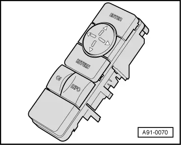
‒ → Select the menu item "SYS. TEST" with the cursor keys.
Display:
|
|
|
|
SERV. MENU:
SET WHLS
WIRING
DRIVE TST
> SYS. TEST
END
|
|
-
‒ Confirm the selection with the "ENTER" key.
Display:
|
CHECK:
A4 - SAL - B5
TYRE:
205/60 15
|
|
|
> YES
NO
|
|
-
‒ If the selection is confirmed with the "ENTER" key, the program continues with the relevant menu item.
-
‒ If the selection is not confirmed with the "ENTER" key, the following instruction appears:
Display:
|
CARRY OUT
WHEEL
CALIBRATION!
|
|
|
> OK
|
|
-
‒ Confirm the display OK with the "ENTER" key.
Display:
|
|
|
|
SYS. TEST
> PARAMETER
WH. SENSOR
COMPASS
SHUNT
INTERNAL
|
|
Notes:
-
◆ It is possible to perform either the complete system test or individual test steps only.
-
◆ The "SYS. TEST" menu can only be quit by pressing the "RETURN" key.
Invoking the current parameters
Note:
The current parameters can be checked to ensure correct settings or to detect missing or incorrect settings/calibrations (e.g. a wrongly selected vehicle type) which can lead to poor navigation performance or complete failure of the navigation system.
Test requirements:
-
◆ The displays for vehicle type, track width and tyre type must correspond to the actual conditions.
-
◆ Calibration values from the test drive must be available, i.e. the test drive must be performed beforehand.
-
‒ Select the menu item "PARAMETER" with the cursor keys.
Display:
|
|
|
|
SYS. TEST
> PARAMETER
WH. SENSOR
COMPASS
SHUNT
INTERNAL
|
|
-
‒ Confirm the selection with the "ENTER" key.
Display:
|
VEHICLE:
---------------
|
|
|
A4 - SAL - B5
---------------
> CONTINUE
|
|
-
‒ If there are no faults, press the "ENTER" key to continue the parameter test.
If there are faults, this means that the specifications on the display do not correspond to the actual vehicle type.
-
‒ Perform wheel calibration => Page 91-161
Display:
|
|
|
|
REAR TRACK
WIDTH:
---------------
1479 MM
> CONTINUE
|
-
‒ If there are no faults, press the "ENTER" key to continue the parameter test.
If there is a fault, this means that the displayed track width does not correspond to the vehicle type (deviations > 1%).
Possible track widths => Track width table, Page 91-171
-
‒ Perform wheel calibration => Page 91-161
Note:
For special tyre types, select the menu item "SPECIAL".
.
Notes:
-
◆ The actual circumference of new tyres is within a tolerance of ± 1 % and adapts itself as fully as possible when the navigation system is operating.
-
◆ Deviations from the specified circumferences for new tyres are thus normal and reflect the adaption process.
-
◆ The displayed tyre circumference only deviates widely from the usual circumferences if the calibration is grossly inaccurate (due to a wrongly entered route length being driven).
A tyre circumference should only be corrected via wheel calibration if this is the case, or if permanent length errors are identified by the customer.
Range of typical tyre circumferences .
Table of typical tyre circumferences:
|
|
|---|
|
Tyre type
for
|
typical circumferences of new tyres
(after wheel calibration)
|
|
A8-D2
|
2050 - 2080
|
|
A6-C5
|
1900 - 1970
|
|
A4-B5
|
1900 - 1940
|
|
A3-AB
|
1900 - 1940
|
Note:
If the tyres have been used, the typical circumferences may deviate from the specified values.
Display:
|
|
|
|
TYPE OF TYRE:
---------------
205/60 15
---------------
C: 1910 MM
> CONTINUE
|
-
‒ Press "ENTER" key to continue.
Possible tyre sizes and tyre circumferences =>Tyre table, Page 91-166
If a fault occurs, this means that the displayed tyre type does not correspond to the actual tyres.
-
‒ Perform wheel calibration => Page 91-161
Note:
For special tyre types, select the menu item "SPECIAL".
.
Display:
|
|
|
|
DRIVE TST
---------------
HAS BEEN
CARRIED OUT!
> OK
|
-
‒ If there are no faults, press the "ENTER" key to terminate the parameter test.
If there is a fault ("MISSING" is displayed), this means that the test drive has not been performed.
-
‒ Perform test drive => Page 91-196
Wheel pulse test
The speeds of the left and right wheels are displayed when the wheel pulses are checked.
The function for detecting a change in direction (forward or reverse driving) is also checked.
Test requirements:
-
◆ Driving straight ahead at a speed of
> 20 km/h.
-
◆ Reverse approx. 3 m for reverse gear detection.
-
‒ Select the menu item "WH. SENSOR" with the cursor keys.
Display:
|
|
|
|
SYS. TEST
PARAMETER
> WH. SENSOR
COMPASS
SHUNT
INTERNAL
|
|
-
‒ Confirm the selection with the "ENTER" key.
Display:
|
|
|
|
DRIVE AT
CONSTANT
SPEED ANDCOMPARE
> CONTINUE
|
|
-
‒ Press "ENTER" key to continue.
Display:
|
|
|
|
BOTH WHEEL
SPEEDS WITH-SPEEDOMETER.
> OK
|
|
-
‒ Confirm the display OK with the "ENTER" key.
Display:
-
‒ Start the engine and drive forwards straight ahead. Compare the displays of both L and R wheel sensors.
Notes:
-
◆ The permissible difference in the lower speed range between the left (L) and right (R) wheel speeds must not exceed 5 km/h.
-
◆ If the difference is greater than 5 km/h, the output signals from the ABS control unit must be checked.
=> Running gear self-diagnosis; Repair group 01; Self-diagnosis, Electrical test
-
◆ The wheel pulse test must be repeated => Page 91-225.
-
‒ Confirm the display OK with the "ENTER" key if the values are within the permissible range.
Display:
-
‒ Engage reverse gear.
-
‒ Reverse the vehicle approx. 3 m and stop.
-
‒ Confirm the display OK with the "ENTER" key.
If the test is OK, the system will proceed with the compass test => Page 91-230.
If there is a fault with the reverse gear detection, the following will appear on the display:
-
‒ Confirm the display OK with the "ENTER" key.
-
‒ Check signal from reversing light switch according to current flow diagram and repeat wheel pulse test => Page 91-225.
Compass test
The compass wiring is internally checked first in the compass test.
The compass directions are checked in the subsequent drive along a circular route.
Test requirements:
-
◆ An area which is as unobstructed and level as possible (inclination up to max. 4°).
-
◆ Avoid magnetic or electromagnetic interference fields, i.e. anywhere in the vicinity of power lines, a line of trucks, reinforced concrete buildings or iron aggregates (e.g. scrap, steel scaffolding etc.).
-
◆ Driving speed approx. 20 ... 30 km/h
-
◆ The driving route should ideally be a circle with a minimum diameter of 30 m.
It is also possible to drive along a rectangular route.
-
‒ Select the menu item "COMPASS" with the cursor keys.
Display:
|
|
|
|
SYS. TEST
PARAMETER
WH. SENSOR
>COMPASS
SHUNT
INTERNAL
|
|
-
‒ Confirm the selection with the "ENTER" key.
The interior wiring test is then performed.
If no fault occurs, the compass test automatically continues.
If a fault occurs, i.e. no compass data is recognised, the following fault message appears on the display:
Fault message on display:
|
|
|
|
NO COMPASS
DATA-
AVAILABLE.
> CONTINUE
|
|
-
‒ Press "ENTER" key to continue.
Display:
|
|
|
|
CHECK
COMPASS-
AND CABLE.
> OK
|
|
-
‒ Check the compass wiring according to the current flow plan and repair if necessary. Restart the compass test => Page 91-230.
The compass test is automatically continued if the wiring is OK.
Display:
|
|
|
|
DRIVE
SLOWLY IN
A CIRCLE.
> START
|
|
-
‒ Confirm the display "Start" with the "ENTER" key.
Display:
-
‒ Drive along the route according to the test requirements => Page 91-230 and confirm completion at the end of the route by pressing the "ENTER" key.
The following display appears once the compass test has been completed successfully:
If the compass test is OK, the system will proceed with the shunt resistor test => Page 91-238.
If the compass data is not OK, one of the following three causes of the fault will be displayed:
-
‒ Press "ENTER" key to continue.
1st Cause "Compass unusable"
The compass ellipse recorded is unusable.
This is due to magnetic interference or a defective magnetic field probe.
-
‒ Press "ENTER" key to continue.
2nd Cause "Route was too short"
|
|
|
|
ERROR:
DISTANCE
WAS TOO
SHORT.
CONTINUE
|
|
The diameter of the circle was too small or the vehicle was driven too fast.
-
‒ Use the "ENTER" key to continue and repeat compass test correctly => Page 91-230.
3rd Cause "Circle incomplete"
|
|
|
|
ERROR:
CIRCLE
INCOMPLETE-
> CONTINUE
|
|
No complete circle was recognised.
-
‒ Use the "ENTER" key to continue and repeat compass test correctly => Page 91-230.
Shunt resistor test or voltage tap test
Notes:
-
◆ A shunt resistor has been installed in the A4 Saloon.
-
◆ A voltage tap has been installed at the rear window of the A4 Avant, i.e. the battery voltage is measured.
The wiring and the resistance values are checked in the shunt resistor test or voltage tap test by switching the rear window heating on and off (approx. 2-3 seconds).
-
‒ Select the menu item "SHUNT" or "REAR VOLT." with the cursor keys.
Display:
|
|
|
|
SYS. TEST
PARAMETER
WH. SENSOR
COMPASS
> SHUNT
INTERNAL
|
|
-
‒ Confirm the selection with the "ENTER" key.
Next display:
|
|
|
|
REAR
WINDOW-
HEATING
ON!
> OK
|
|
-
‒ Switch on rear window heating and confirm with the "ENTER" key.
Next display:
|
|
|
|
REAR
WINDOW-
HEATING
OFF!
> OK
|
|
-
‒ Switch off rear window heating and confirm with the "ENTER" key.
If the shunt resistor test or voltage tap test is OK, the selection menu for the system test reappears.
However, if the following display appears:
|
|
|
|
NO REAR
WINDOW-
READING.
CHECK
PLUG!
> CONTINUE
|
|
Switch for heated rear window has not been actuated or
-
‒ check the connectors to the switch or rear window heating according to the current flow diagram and repair if necessary.
-
‒ Press the "ENTER" key to continue and repeat shunt resistor test or voltage tap test => Page 91-238.
Interior control unit test
Interior control unit components and the GPS aerial signals are checked in this test.
-
‒ Select the menu item "INTERIOR" with the cursor keys.
Display:
|
|
|
|
SYS. TEST
PARAMETER
WH. SENSOR
COMPASS
SHUNT
> INTERNAL
|
|
-
‒ Confirm the selection with the "ENTER" key.
Display:
|
|
|
|
INTERNAL
HARDWARE-
TEST...
(1 - 4 MIN.)
> START
|
|
-
‒ Press the "ENTER" key to start the interior test.
Display:
|
|
|
|
INTERNAL
TESTS
RUNNING.
PLEASE
WAIT...
|
|
Please wait for the next display.
The following display appears once the control unit test has been completed successfully:
-
‒ Press the "ENTER" key to continue and terminate the system test.
However, if faults occur during the control unit test, one of the following fault messages appears:
1st Cause "No signals from GPS aerial"
|
|
|
|
NO SIGNALS
FROM GPS
AERIAL!-
> CONTINUE
|
|
-
‒ Test connector and wiring of GPS aerial according to current flow diagram and repair if necessary.
-
‒ If there is no fault in the wiring, check the GPS aerial and replace if necessary.
-
‒ Use the "ENTER" key to continue and repeat interior control unit test => Page 91-241.
2nd Cause "Navigation unit defective"
|
|
|
|
NAVIGATION
UNIT
FAULTY.
PLEASE
REPLACE!
> CONTINUE
|
|
-
‒ Replace navigation system control unit.
Note:
If replacing the navigation system control unit, observe the requisite measures => Page 91-148.
-
‒ Use the "ENTER" key to continue and repeat interior control unit test => Page 91-241.
Terminate system test
Display:
|
|
|
|
SYS. TEST
PARAMETER
WH. SENSOR
COMPASS
SHUNT
> INTERNAL
|
|
-
‒ Press the "RETURN" key to terminate the system test.
Display:
|
|
|
|
SERV. MENU:
SET WHLS
WIRING
DRIVE TST
SYS. TEST
> END
|
|
|