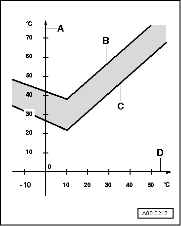
- → B - Specified vent temperature at 2/3 of maximum temperature setting
- C - Specified vent temperature at 1/3 of maximum temperature setting
- D - Ambient temperature
Example: At 2/3 of max. specified vent temperature (measured values of senders -G150, -G151, -G261, -G262)
|
|
|---|
|
Ambient temperature in °C (measured value of -G89)
|
Specified vent temperature in °C
|
|
approx. 0
|
approx. 42
|
|
approx. 10
|
approx. 38
|
|
approx. 45
|
approx. 72
|
Notes:
-
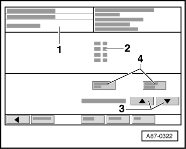
◆ If required values are not attained, compare measured values indicated in display group "009" zones "1, 2, 3" and "4":
-
‒ If measured values in display zones "1" and "3" or "2" and "4" are OK, check temperature flap control motor for side on which measured value is not OK (-V158 or -V159). To do so, perform electrical check on temperature flap control motors (-V158 or -V159)
=> Page 01-247 "Electrical Check, Test Step 4".
-
‒ Check senders -G150, -G151, -G261 and -G262 for proper installation and electrical connections for contact resistance => Page 01-247 "Electrical Check, Test Step 4". Replace any defective components.
-
‒ Check operation of levers between control motors and flaps
=> Page 80-57.
-
◆ Temperature of air flow from "Centre" dash panel vents can also be measured using Minitester V.A.G 1362, for example.
-
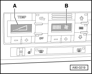
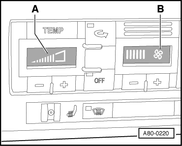
◆ Respective temperatures for left/right side can be synchronised by simultaneously pressing buttons "+" and "-" for temperature preselection on operating and display unit for air conditioner/Climatronic -E87 (heating).
|