|
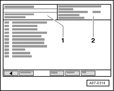
→ Indicated on display of VAS 5051:
-
◆ Display zone -1- shows which control element is currently being actuated (e.g. 1st control element in test).
-
◆ Display zone -2- gives a consecutive list of control elements already actuated and the one currently being actuated. The one currently being actuated appears in the bottom line.
-
‒ Touching the ⇒key selects the next component. Function and sequence =>Table of control elements actuated, Page 01-89.
Notes:
-
◆ Return to selection program by touching ←key.
-
◆ Final control diagnosis can be terminated by pressing C-key.
-
◆ On completion of final control diagnosis, interrogate fault memory => Page 01-18.
-
◆ If final control diagnosis is aborted, interrogate fault memory
=> Page 01-114 (display group 002).
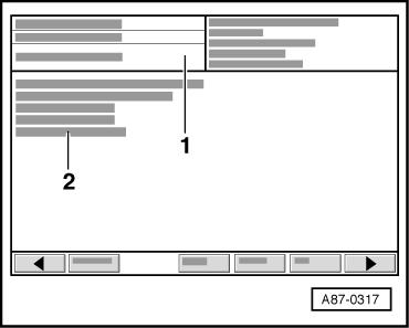
Control elements actuated
|
|
|---|
|
Indicated on display
|
Specified function
|
Fault remedy
|
|
Fresh-air blower -V2
|
- Fresh-air blower -V2 runs
Fresh-air blower speed constantly changes within 8 sec. between 0% and 88% of maximum speed
|
- Check freedom of movement of fresh-air blower
Use current flow diagram to check positive and earth connection for fresh-air blower control unit -J126
Check fresh-air blower control unit -J126
=> Page 80-18
|
|
|
|---|
|
Indicated on display
|
Specified function
|
Fault remedy
|
|
Temperature flap control motor, left -V158
|
- Control motor -V158 moves from stop to stop
|
- Check freedom of movement of left temperature flap
|
|
- Open all dash panel vents
|
- Fresh-air blower runs at approx. 60% of maximum speed
Temperature of air from left vents changes (with warm engine)
|
- Use current flow diagram to check for open circuit in wiring between temperature flap control motor, left -V158 and operating and display unit for air conditioner/Climatronic -E87 (heating) or for interchanged wiring
Check temperature flap control motor, left -V158 =>Electrical check, Page 80-18
|
|
Temperature flap control motor, right -V159
|
- Control motor -V159 moves from stop to stop
|
- Check freedom of movement of right temperature flap
|
|
- Open all dash panel vents
|
- Fresh-air blower runs at approx. 60% of maximum speed
Temperature of air from right vents changes (with warm engine)
|
- Use current flow diagram to check for open circuit in wiring between temperature flap control motor, right -V159 and operating and display unit for air conditioner/Climatronic -E87 (heating) or for interchanged wiring
Check temperature flap control motor, right -V159 =>Electrical check, Page 80-18
|
|
|
|---|
|
Indicated on display
|
Specified function
|
Fault remedy
|
|
Central flap control motor
-V70
|
- Control motor -V70 moves from stop to stop
|
- Check freedom of movement of central flap
|
|
- Open all dash panel vents
|
- Fresh-air blower runs at approx. 60% of maximum speed
Air distribution is switched from footwell/defrost to dash panel vents
|
- Use current flow diagram to check wiring between control motor -V70 and operating and display unit for air conditioner/Climatronic -E87 (heating) for open circuit or interchanged wiring
Check central flap control motor -V70
=>Electrical check, Page 80-18
|
|
Defrost flap control motor
-V107
|
- Control motor -V107 moves from stop to stop
|
- Check freedom of movement of footwell/defrost flap
|
|
|
- Fresh-air blower runs at approx. 60% of maximum speed
- Central flap is closed
Air distribution is switched from footwell to defrost
|
- Use current flow diagram to check wiring between control motor -V107 and operating and display unit for air conditioner/Climatronic -E87 (heating) for open circuit or interchanged wiring
Check defrost flap control motor -V107
=>Electrical check, Page 80-18
|
|
|
|---|
|
Indicated on display
|
Specified function
|
Fault remedy
|
|
Air-flow flap control motor
-V71
|
- Control motor -V71 moves from stop to stop
|
- Check freedom of movement of air-flow/fresh-air flaps
|
|
- Open all dash panel vents
|
- Fresh-air blower runs at approx. 60% of maximum speed
- Recirculated-air flap is closed
Air-flow/fresh-air flaps open and close
Air flow from vents changes
|
- Use current flow diagram to check for open circuit in wiring between control motor -V71 and operating and display unit for air conditioner/Climatronic -E87 (heating) or for interchanged wiring
Check air-flow flap control motor -V71
=>Electrical check, Page 80-18
|
Notes:
-
◆ This control motor is only fitted on left-hand drive vehicles for actuating air flow/fresh-air flaps.
-
◆ Right-hand drive vehicles are not equipped with this control motor. If this control motor is displayed for RHD vehicle, check encoding of -E87 (heating) =>Reading measured value block, Page 01-114 (display group 019).
|
|
|---|
|
Indicated on display
|
Specified function
|
Fault remedy
|
|
Air recirculation flap control motor -V113
|
- Control motor -V113 moves from stop to stop
|
- Check freedom of movement of recirculated-air flap (and fresh-air flaps)
|
|
- Open all dash panel vents
|
- Fresh-air blower runs at approx. 60% of maximum speed
- Fresh-air and air-flow flap is closed
Recirculated-air flap (and fresh-air flap) opens and closes
Air flow from vents changes (LHD)
Air is drawn in alternately in passenger's footwell or via dust and pollen filter (RHD)
|
- Use current flow diagram to check for open circuit in wiring between control motor
-V113 and operating and display unit for air conditioner/Climatronic -E87 or for interchanged wiring
Check air recirculation flap control motor
-V113 => Electrical check, Page 80-18
|
Notes:
-
◆ On left-hand drive vehicles, control motor -V113 is only used to move recirculated air flap. Air flow/fresh-air flaps are moved by control motor -V71.
-
◆ On right-hand drive vehicles, air recirculation flap control motor -V113 moves both recirculated-air flap and fresh-air flaps. These vehicles do not feature air-flow control and are not fitted with control motor -V71.
|
|
|---|
|
Indicated on display
|
Specified function
|
Fault remedy
|
|
Segment test
|
- All display segments, function feedback lamps in buttons and illumination of operating and display unit for air conditioner/Climatronic -E87 (heating) are switched on and off every 2 seconds
|
- Replace operating and display unit for air conditioner/Climatronic -E87 (heating)
=> Page 80-18
|
|
Heated rear window -Z1
|
- Heated rear window is activated once for 10 s
Rear window becomes warm around heater wires
|
- Check actuation and current input of heated rear window -Z1 =>Electrical Check, Page 80-18
|
Notes:
-
◆ Activation function of -E87 (heating) for heated rear window can be checked, for example, during final control diagnosis using multimeter V.A.G 1715. Connect current probe via positive wire from -E87 (heating) to heated rear window -Z1 and select "Current measurement via current probe" function on multimeter. Reading changes from approx. 0 A to greater than 7A.
-
◆ If control element "Heated windscreen" is displayed following control element "Heated rear window", check encoding of operating and display unit for air conditioner/Climatronic -E87 (heating) => Page 01-107. Heated windscreen is not available at present, but -E87 (heating) already contains this feature so as to be able to actuate this output for final control diagnosis by way of possible future code.
|
|
|---|
|
Indicated on display
|
Specified function
|
Fault remedy
|
|
END
|
Info display
End of control element test for vehicles with no heated seats and no heated windscreen
|
|
|
Heated windscreen -Z2
|
- Heated windscreen control unit
- -J505 is actuated for approx. 10 s
Control unit -J505 switches on heated windscreen -Z2 if electrical system voltage is greater than 12.70 V
|
- Read measured value block
|
Notes:
-
◆ If this control element is actuated for vehicles with no heated windscreen, check encoding of operating and display unit for air conditioner/Climatronic -E87 (heating) => Page 01-107.
-
◆ During final control diagnosis, heated windscreen is only actuated by -E87 (heating) up to a passenger compartment temperature of 40° C. If temperature is higher, "Function unknown or cannot be implemented at present" appears on fault reader display.
-
◆ Cut-in function of control unit -J505 can be checked for example using multimeter V.A.G 1715. Connect current probe via positive wire from control unit -J505 to heated windscreen -Z2 and select "Current measurement via current probe" function on multimeter. Reading changes from approx. 0 A to greater than 7A.
-
◆ Operation of heated windscreen =>Reading measured value block, display group 015, Page 01-283.
|
|
|---|
|
Indicated on display
|
Specified function
|
Fault remedy
|
|
END
|
Info display
End of control element test for vehicles with no heated seats
|
|
|
|
|---|
|
Indicated on display
|
Specified function
|
Fault remedy
|
|
Heated driver's seat -Z6
|
- Driver's seat heating element is actuated for approx. 10 s
|
- Use current flow diagram to check earth connection to heating element in heated driver's seat -Z6
Use current flow diagram to check wiring between -E87 (heating) and -Z6
Check actuation and current input of heated driver's seat -Z6 =>Electrical check, Page 80-18
|
Notes:
-
◆ Seat heating is only actuated in the case of operating and display unit for air conditioner/Climatronic -E87 (heating) which is fitted with a seat heating potentiometer (heed part number and index).
-
◆ Cut-in function for seat heating can be checked for example using multimeter V.A.G 1715. Connect current probe via positive wire to seat heating element and select "Current measurement via current probe" function on multimeter. Reading changes from approx. 0 A to greater than 2A.
|
|
|---|
|
Indicated on display
|
Specified function
|
Fault remedy
|
|
Heated front passenger's seat -Z8
|
- Front passenger's seat heating element is actuated for approx. 10 s
|
- Use current flow diagram to check earth connection to heating element in heated front passenger's seat -Z8
Use current flow diagram to check wiring between -E87 (heating) and -Z8
Check actuation and current input of heated front passenger's seat -Z8 =>Electrical check, Page 80-18
|
|
END
|
Info display
End of final control test
|
|
Notes:
-
◆ Seat heating is only actuated in the case of operating and display unit for air conditioner/Climatronic -E87 (heating) which is fitted with a seat heating potentiometer (heed part number and index).
-
◆ Cut-in function for seat heating can be checked for example using multimeter V.A.G 1715. Connect current probe via positive wire to seat heating element and select "Current measurement via current probe" function on multimeter. Reading changes from approx. 0 A to greater than 2A.
|