
A4 Mk2
|
Basic setting
Basic setting
Requirements:
|
 |
|
→ Indicated on display of V.A.S 5051:
|
 |
|
|
→ Indicated on display of V.A.S 5051:
|
 |
|
|
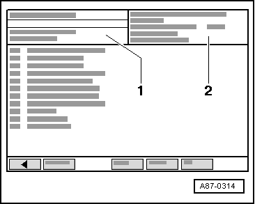
→ Indicated on display of V.A.S 5051: The following control motors are now actuated and their current feedback value displayed in zone 1. At present, the control motors are assigned as follows:
|
|
|
|
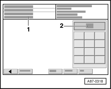
→ Indicated on display of V.A.S 5051:
End positions of control motors (resistance values on stop) are stored in operating and display unit for air conditioner/Climatronic -E87 (heating) (resistance value of potentiometers in control motors) and used for further control action. Once control motors have reached both end stops, they are moved again from one stop to the other. During this process, adjustment time is measured and stored in -E87 (heating) for use in the event of emergency operation. |
|
|
|
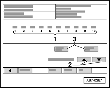
→ Indicated on display of V.A.S 5051: Movement of control motors can be followed on display in display zone -1- (feedback values in display zones 1 - 6 change). Wait until "0" is indicated for feedback values displayed in zone -1-. Notes:
|
|
|
Note: If a fault has been detected and eliminated, basic setting is to be repeated. |