
A4 Mk2
| Clutch release mechanism - Exploded view |

| 1 - | Slave cylinder |
| q | Do not operate clutch pedal after slave cylinder has been removed. |
| q | Removing and installing → Chapter |
| q | When installing, press in slave cylinder so that securing bolt can be fitted easily |
| q | Grease lightly before installing → Anchor |
| q | Disconnecting pipe/hose assembly → Anchor |
| q | Follow correct procedure when bleeding → Chapter |
| q | Tighten bleeder valve to 4.5 Nm. |
| 2 - | Hexagon socket head bolt |
| q | 23 Nm |
| q | Slave cylinder to gearbox |
| q | Self-locking |
| q | Always renew |
| 3 - | Bracket |
| q | For pipe/hose assembly |
| q | Attached to gearbox together with slave cylinder |
| q | Installing → Fig. |
| 4 - | Plunger |
| q | Lubricate end of plunger with copper grease -Z 381 351 TE- |
| 5 - | Dished spring |
| q | Smaller diameter (convex side) faces guide sleeve |
| 6 - | Input shaft oil seal |
| q | Available as replacement part together with guide sleeve → Item. |
| q | Pack space between sealing lip and dust lip half full with sealing grease -G 052 128 A1-. |
| 7 - | Torx socket head bolt |
| q | Self-locking |
| q | Renew |
| q | Black: only for aluminium gearboxes |
| q | Bright metal: for aluminium and magnesium gearboxes |
| q | For correct version, refer to → Electronic parts catalogue |
| q | Tighten to 35 Nm on aluminium gearboxes |
| q | Tighten to 25 Nm on magnesium gearboxes |
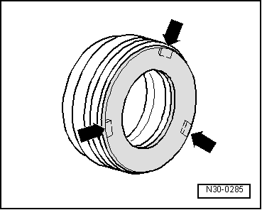
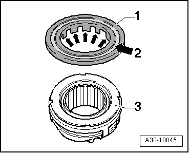
| 8 - | Release bearing |
| q | With or without plastic ring, depending on design |
| q | Checking and servicing release bearing with glued plastic ring → Fig. |
| q | Checking release bearing with mechanically attached plastic ring → Fig. |
| q | Renew if groove worn on plastic ring is too deep → Fig. |
| q | Do not wash out bearing; wipe clean only |
| q | Renew bearing if noisy |
| q | Retainer lugs on release bearing must engage in release lever |
| 9 - | Clutch release lever |
| q | Before installing, lubricate area which makes contact with plunger of slave cylinder with copper grease -Z 381 351 TE-. |
| 10 - | Retaining spring |
| q | Secure to clutch release lever |
| 11 - | Guide sleeve |
| q | Available as replacement part together with oil seal → Item. |
| q | Installation position: Oil drain hole points downwards. |
| q | Before removing and installing, cover input shaft splines with a shrink-fit hose to protect oil seal → Item. |
| q | Guide sleeve is made of different materials for aluminium and magnesium gearboxes |
| q | For correct version, refer to → Electronic parts catalogue |
| 12 - | O-ring |
| q | Renew |
| 13 - | Intermediate piece |
| 14 - | Ball head stud |
| q | Ball head stud is made of different materials for aluminium and magnesium gearboxes |
| q | Lubricate with MoS2 grease |
| q | Tighten to 25 Nm on aluminium gearboxes |
| q | Tighten to 18 Nm on magnesium gearboxes |
| q | For correct version, refer to → Electronic parts catalogue |
| 15 - | Gearbox |
 Note
Note
|
|