
A4 Mk2
| Dismantling and assembling pinion shaft up to 05.03 |
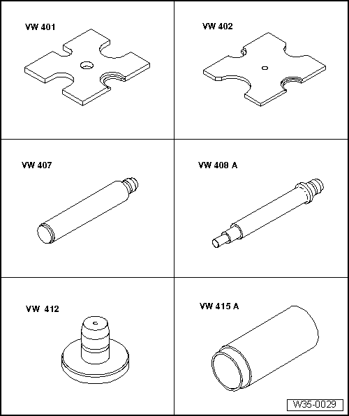
| Special tools and workshop equipment required |
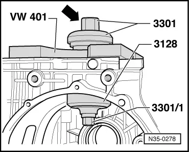
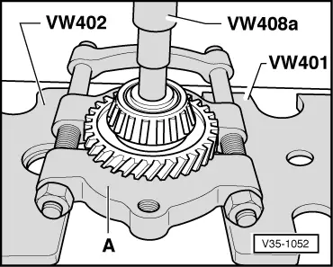
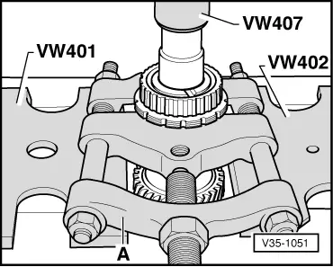
| t | Thrust plate -VW 401- |
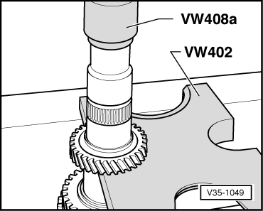
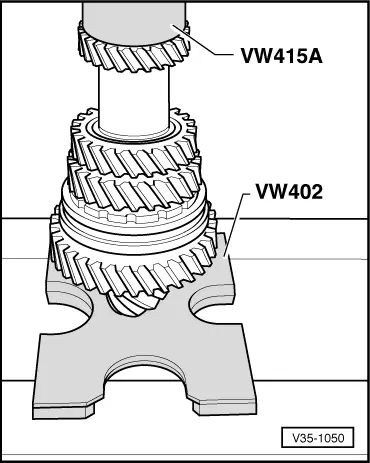
| t | Thrust plate -VW 402- |
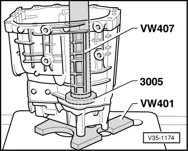
| t | Press tool -VW 407- |
| t | Press tool -VW 408 A- |
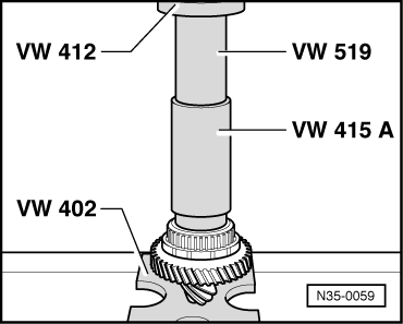
| t | Press tool -VW 412- |
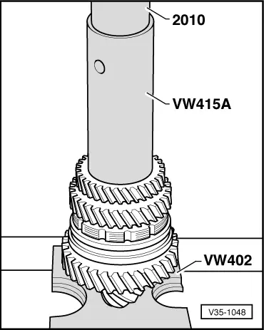
| t | Tube -VW 415 A- |
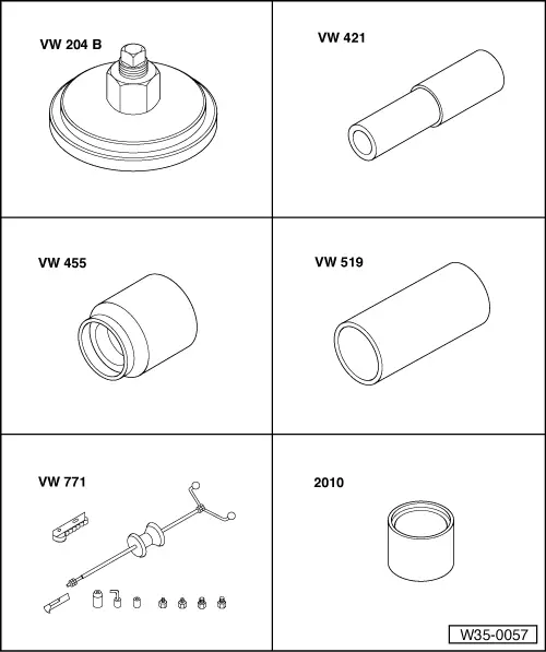
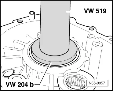
| t | Crankshaft seal installing tool -VW 204 B- |
| t | Tube -VW 421- |
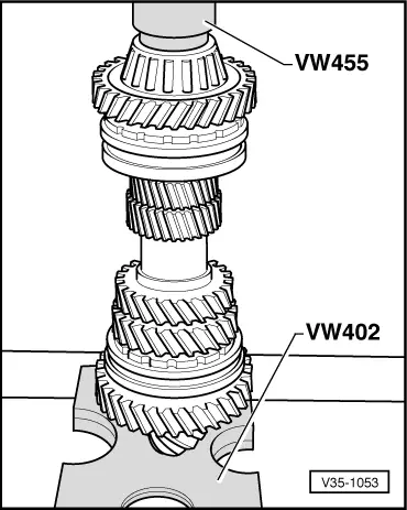
| t | Installing sleeve -VW 455- |
| t | Tube -VW 519- |
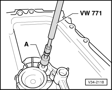
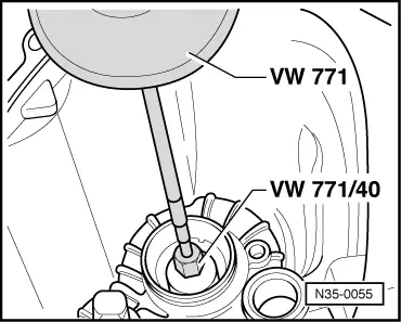
| t | Multi-purpose tool -VW 771- |
| t | Tube -2010- |
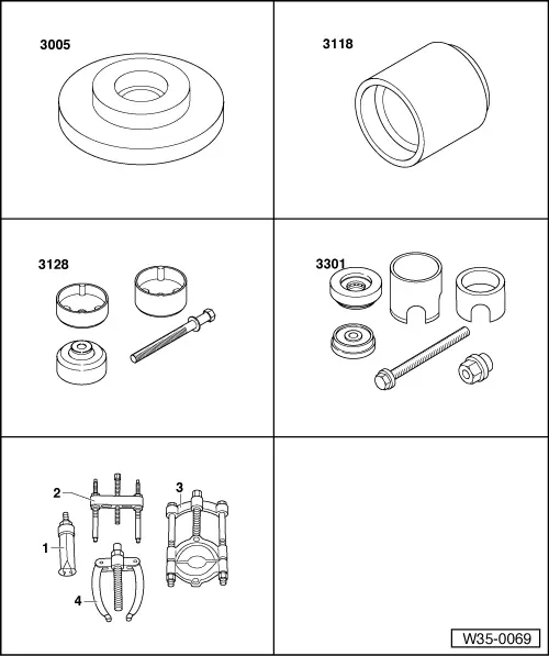
| t | Thrust plate -3005- |
| t | Press tool -3118- |
| t | Fitting tool -3128- |
| t | Assembly tool -3301- |
| t | -1-Internal puller -Kukko 21/1- |
| t | -1-Internal puller -Kukko 21/4- |
| t | -3-Splitter -Kukko 17/2- |
 Note
Note| t | From 05.03 onwards, a new type of synchromesh for 1st and 2nd gear as well as for 5th and reverse gear is fitted. Dismantling and assembling pinion shaft from 05.03 → Chapter. |
| t | Refer to technical data → Chapter when installing new gear wheels or the final drive gear set. |
| t | Adjustment work is required when renewing the parts marked with 1) → Chapter „Table of adjustments“. |
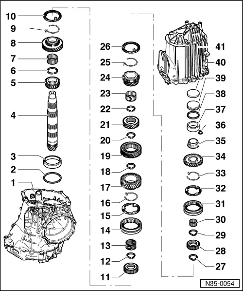
| 1 - | Gearbox housing 1) |
| q | Housing manufactured from aluminium or magnesium → Item |
| 2 - | Shim “S3” |
| q | Table of adjustments → Chapter |
| 3 - | Outer race for large tapered roller bearing 1) |
| q | Pulling out → Fig. |
| q | Pressing in → Fig. |
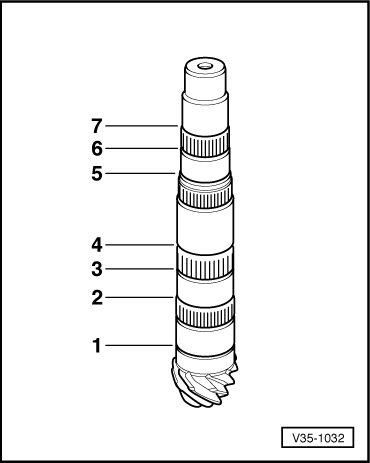
| 4 - | Pinion shaft 1) |
| q | Is mated with crown wheel, always renew together as a set |
| q | Adjusting pinion shaft and crown wheel → Chapter |
| 5 - | Inner race for large tapered roller bearing 1) |
| q | Renew |
| q | Will be damaged during removal |
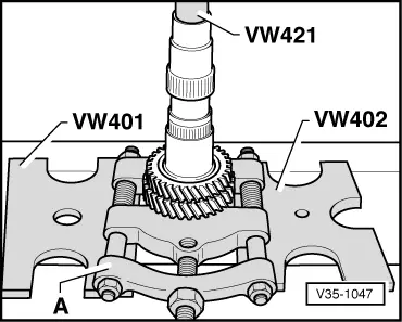
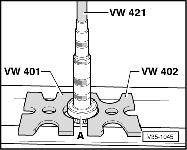
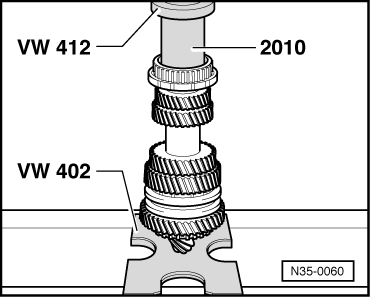
| q | Pressing off → Fig. |
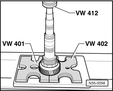
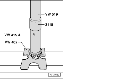
| q | Pressing on → Fig. |
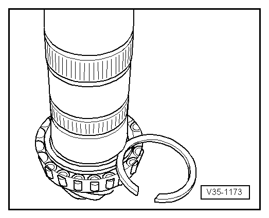
| 6 - | Circlip |
| q | Mark |
| q | Installation position → Fig. |
| q | Re-determine thickness if tapered roller bearing is renewed → Fig. |
| 7 - | Needle bearing for 1st gear |
| 8 - | 1st speed selector gear |
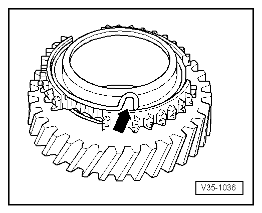
| 9 - | Spring |
| q | Insert in 1st speed selector gear → Fig. |
| q | Allocation to selector gear → Electronic parts catalogue |
| 10 - | Synchro-ring for 1st gear |
| q | Checking for wear → Fig. |
| 11 - | Synchronising hub for 1st and 2nd gear |
| q | Pressing off → Fig. |
| q | Pressing on → Fig. |
| 12 - | Circlip |
| q | Mark |
| q | Installation position → Fig. |
| q | Redetermine thickness if synchronising hub is replaced → Fig. |
| 13 - | Needle bearing for 2nd gear |
| 14 - | Locking collar for 1st and 2nd gear |
| q | Installation position → Fig. |
| 15 - | Synchro-ring for 2nd gear |
| q | Checking for wear → Fig. |
| 16 - | Spring |
| q | Insert in 2nd speed selector gear → Fig. |
| q | Allocation to selector gear → Electronic parts catalogue |
| 17 - | 2nd speed selector gear |
| 18 - | Circlip |
| q | Mark |
| q | Installation position → Fig. |
| 19 - | 3rd gear wheel |
| q | Pressing off → Fig. |
| q | Groove faces 4th gear |
| q | Pressing on → Fig. |
| 20 - | Circlip |
| q | Mark |
| q | Installation position → Fig. |
| q | If 3rd gear wheel is renewed redetermine thickness → Fig. |
| 21 - | 4th gear wheel |
| q | Pressing off → Fig. |
| q | Shoulder faces towards 3rd gear |
| q | Pressing on → Fig. |
| 22 - | Circlip |
| q | Mark |
| q | Installation position → Fig. |
| q | If 4th gear wheel is renewed redetermine thickness → Fig. |
| 23 - | Needle bearing |
| 24 - | 5th speed selector gear |
| 25 - | Spring |
| q | Insert in 5th speed selector gear → Fig. |
| q | Allocation to selector gear → Electronic parts catalogue |
| 26 - | Synchro-ring for 5th gear |
| q | Checking for wear → Fig. |
| 27 - | Circlip |
| q | Mark |
| q | Installation position → Fig. |
| 28 - | 5th gear and reverse gear synchronising hub |
| q | Pressing off → Fig. |
| q | Pressing on → Fig. |
| 29 - | Circlip |
| q | Mark |
| q | Installation position → Fig. |
| q | Redetermine thickness if synchronising hub is replaced → Fig. |
| 30 - | Needle bearing |
| q | For reverse gear |
| 31 - | Locking collar for 5th and reverse gear |
| q | Installation position → Fig. |
| 32 - | Synchro-ring for reverse gear |
| q | Checking for wear → Fig. |
| 33 - | Spring |
| q | Insert in reverse selector gear → Fig. |
| q | Allocation to selector gear → Electronic parts catalogue |
| 34 - | Reverse selector gear |
| 35 - | Inner race for small tapered roller bearing 1) |
| q | Pressing off → Fig. |
| q | Pressing on → Fig. |
| 36 - | Bush |
| q | Secures outer race for small tapered roller bearing |
| q | Pulling out → Fig. |
| q | Need not be refitted after the small taper roller bearing has been renewed |
| 37 - | Outer race for small tapered roller bearing 1) |
| q | Pulling out → Fig. |
| q | Pressing in → Fig. |
| 38 - | Shim “S4” |
| q | Table of adjustments → Chapter |
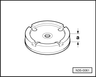
| 39 - | Pressure plate |
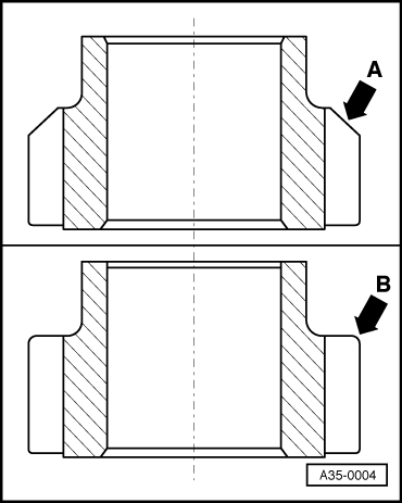
| q | Different thicknesses for aluminium and magnesium gearboxes → Fig. |
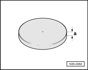
| 40 - | Rubber disc |
| q | Compensates length variations |
| q | To remove, screw self-tapping screw into centre of disc and use screw to pull out disc |
| q | Different thicknesses for aluminium and magnesium gearboxes → Fig. |
| q | Select correct version according to gearbox code letters → Electronic parts catalogue → Chapter |
| 41 - | Gearbox cover |
| q | Aluminium version: must only be fitted to an aluminium gearbox housing |
| q | Magnesium version: must only be fitted to a magnesium gearbox housing |
| q | Note identification markings → Fig. |
| q | Coat sealing surfaces lightly with sealing paste -AMV 188 001 02- |
| q | Can be renewed with gearbox in vehicle → Chapter |
|
|
|
|
|
|
|
|
|
|
|
|
|
|
|
|
|
|
|
|
|
|
|
|
|
|
Note
|
|
| Circlip thickness (mm) | ||
| 2.00 | 2.06 | 2.12 |
| 2.03 | 2.09 | 2.15 |
|
| Circlip thickness (mm) | ||
| 1.90 | 1.96 | 2.02 |
| 1.93 | 1.99 | |
|
| Circlip thickness (mm) | ||
| 2.50 |
|
| Circlip thickness (mm) | ||
| 1.90 | 1.98 | 2.06 |
| 1.94 | 2.02 | |
|
| Circlip thickness (mm) | ||
| 1.86 | 1.94 | |
| 1.90 | 1.98 | |
|
| Circlip thickness (mm) | ||
| 2.00 |
|
| Circlip thickness (mm) | ||
| 1.90 | 1.96 | 2.02 |
| 1.93 | 1.99 | 2.05 |
|
|
|
|
|
|
|
|
|
|
Note
|
|
|
|
|
|
|
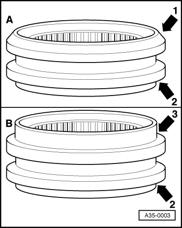
|
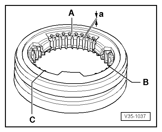
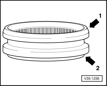
| A | Reverse gear wheel with chamfered surface | Both types of locking collar can be installed (with chamfered surface or with large shoulder) |
| B | Reverse gear wheel without chamfered surface | Install only locking collar with large shoulder; do not use locking collar with chamfered edge |
|
|
| Gearbox housing | Distance -a- |
| Aluminium | 14.8 or 15.3 mm |
| Magnesium → Chapter | 10.7 mm |
|
|
| Gearbox housing | Distance -a- |
| Aluminium | 7.0 mm |
| Magnesium | 11.0 mm |