audi Workshop Repair Guides

Audi Workshop Service and Repair Manuals

Re-determining shim "S4” when renewing gearbox cover > < Re-adjustment sequence for final drive gear set
Adjusting pinion shaft
(Adjusting pinion shaft and hollow shaft)
Repairs after which the pinion shaft must be adjusted → Chapter.
   
Special tools and workshop equipment required
t  Torque wrench -V.A.G 1331-
t  Transmission removal lever -VW 296-
t  Universal measuring tool -VW 385-
t  Universal dial gauge bracket -VW 387-
t  Thrust plate -VW 401-
t  Press tool -VW 407-

   
t  Tube -VW 519-
  W00-0045
t  Assembly device -VW 792-
  W00-0802
t  Thrust pad -3062-
Determining total shim thickness “Stotal” for shims “S3” plus “S4
(Adjustment of pre-load of tapered roller bearings for pinion shaft with hollow shaft)
l  Differential removed
  W00-0581
–  Press double tapered roller bearing inner race -1- onto pinion shaft and secure → Chapter.
–  Fit needle bearing -2-.
–  Fit circlip -3- onto hollow shaft and press on tapered roller bearing inner race -4- → Chapter.
–  Fit pinion shaft in hollow shaft.
  Note
The hollow shaft is shown in the illustration without gears. The adjustment of the pinion shaft can be performed either with or without the gears fitted.
  N39-0509
–  Fit double tapered roller bearing outer race for pinion shaft in gearbox housing without shims.
Smaller diameter of thrust pad -3062- faces outer race.
  V35-1044
–  Press tapered roller bearing outer race for pinion shaft together with a 1.00 mm thick provisional shim “S4*” fully into gearbox cover.
  Note
t  For measurement purposes a shim “S4” with a thickness of 1.0 mm is inserted provisionally. This is referred to in the following as “S4*”. “S4*” is exchanged with the final shim “S4” after determining measured value “e”.
t  When taking measurements, always fit the rubber washer together with the ring for the rubber washer → Item.
–  Fit fully assembled pinion shaft with hollow shaft into gearbox housing.
–  Fit gearbox cover and tighten bolts to 22 Nm.
–  Turn gearbox so that the gearbox cover points downwards.
  N35-0202
–  Press down on face of pinion shaft with transmission removal lever -VW 296- until the outer race for the tapered roller bearing contacts the gearbox cover.
–  While still maintaining pressure, rotate the pinion shaft 5 turns in each direction in relation to the hollow shaft to settle the double tapered roller bearing.
–  Then rotate pinion shaft together with hollow shaft 5 turns in each direction to settle tapered roller bearing.
  V39-1151
–  Mount dial gauge (3 mm measuring range) and set to “0” with 2 mm preload.
–  Use dial gauge extension (length 30 mm).
  Note
The dial gauge extension must contact the machined surface on the face of the pinion.
–  Turn gearbox 180° so that the gearbox cover faces upwards.
–  Rotate pinion shaft together with hollow shaft 5 turns in both directions to settle taper roller bearing. Otherwise the result of the measurement will be incorrect.
  V39-1152
–  Read off play on dial gauge and note reading.
t  Measurement in example: 0.45 mm
  Note
If the measurement has to be repeated, the pinion shaft with the hollow shaft must first be rotated another 5 turns in each direction. Preload dial gauge to 2 mm and set to “0” again.
Formula: “Stotal” = “S4*” + measured value + bearing preload
  V39-1153
Example: 
 Inserted shim “S4*”1.00 mm
+Measured value (example)0.45 mm
+Bearing preload (constant value)0.15 mm
=Total shim thickness “Stot” for “S3” plus “S41.60 mm

Determining thickness of provisional shim “S3*”
  Note
Provisional shim S3* is replaced with final shim S3 after determining measured value “e”.
Formula: “S3*” = “Stotal” – “S4*”
   
Example: 
 Total shim thickness “Stot” for “S3” plus “S41.60 mm
Inserted shim “S4*”1.00 mm
=Thickness of shim “S3*”0.60 mm

–  Remove double tapered roller bearing outer race → Fig..
–  Fit provisional shim “S3*” in gearbox housing and install outer race again → Fig..
–  Insert completely assembled pinion shaft into gearbox housing again.
–  Fit gearbox cover and tighten bolts to 22 Nm.
Checking preload of tapered roller bearings for pinion shaft
–  To settle the tapered roller bearings: rotate pinion shaft together with hollow shaft 5 turns in each direction, then rotate pinion shaft separately in relation to hollow shaft 5 turns in each direction.
   
–  Set up measuring tools and secure with bolt -arrow- to gearbox housing.
–  Set dial gauge (3 mm measuring range) to “0” with 2 mm preload.
–  Loosen gearbox cover bolts and turn pinion shaft several times.
–  If the correct shims have been selected the dial gauge will now indicate the following value:
t  0.05 ... 0.15 mm
–  Tighten gearbox cover bolts again to 22 Nm.
–  Detach measuring equipment.
–  To settle the tapered roller bearings: rotate pinion shaft together with hollow shaft 5 turns in each direction, then rotate pinion shaft separately in relation to hollow shaft 5 turns in each direction.
Determining dimension “e”
  Note
Dimension “e” is required to determine the final shim thickness of “S3” and “S4”.
  V39-1249
–  Set adjustment rings of universal measuring tool -VW 385/1- to the following measurements:
t  Dimension -a- = 35 mm
t  Dimension -b- = 75 mm
  V39-0822
–  Assemble universal measuring tool -VW 385/1- as illustrated.
t  Dial gauge extension -A-, 6.5 mm long
Set master gauge -VW 385/30- to “Ro” according to crown wheel Ø and fit onto measuring tool.
Crown wheel Ø 170 mm: “Ro” = 54.95 mm
–  Set dial gauge (3 mm measuring range) to “0” with 2 mm preload.
  A39-0363
–  Place end measuring plate on face of pinion shaft.
  Note
Ensure plate contact surface fits exactly and is free of oil.
  V39-0853
–  Remove master gauge and insert measuring tool into housing.
t  Dial gauge extension -A- (length = 6.5 mm) must be fitted.
t  Dial gauge faces towards cover for final drive.
–  Fit cover for final drive and tighten 4 bolts to 22 Nm.
–  Using the adjustable ring, move the 2nd centring disc outwards as far as possible so that the measuring tool can still just be turned by hand.
  N39-0851
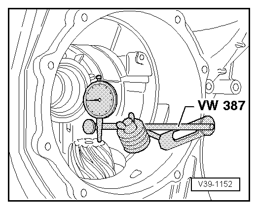
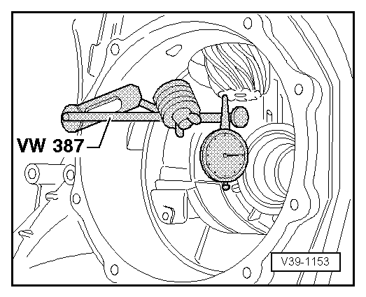
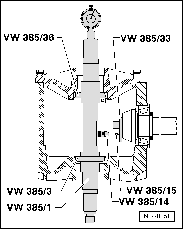
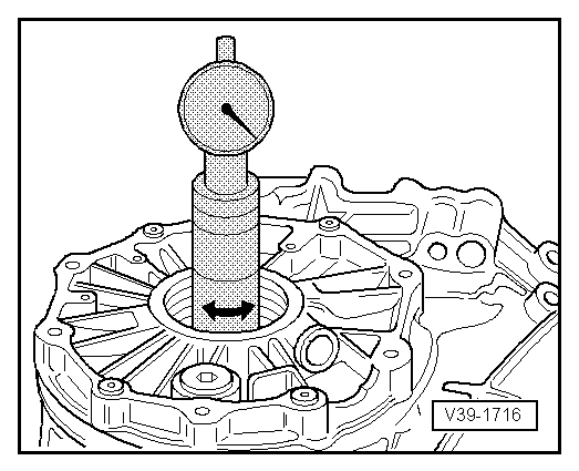
–  Turn measuring tool until tip of dial gauge touches end measuring plate on face of pinion gear, and measure maximum deflection (return point).
t  Measurement in following example: “e” = 0.26 mm (in red scale)
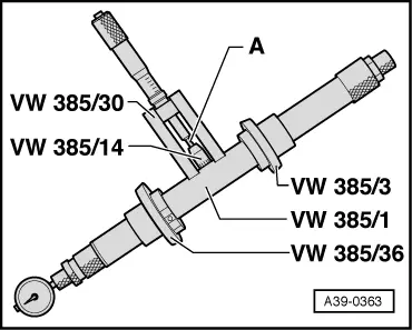
  Note
Then (after removing universal measuring tool), check once again that the dial gauge indicates “0” with 2 mm preload when master gauge -VW 385/30- is in place.
Determining thickness of shim “S3
t  
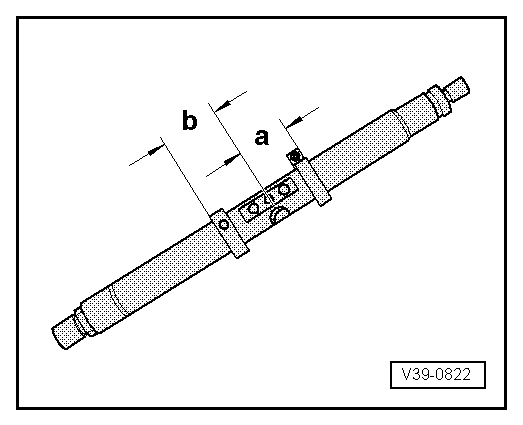
The allowance “r” in relation to the master gauge “Ro” is measured for the final drive gear sets supplied as replacement parts and marked on the outer circumference of the crown wheel.
t  Subtract value “e” if measurement is obtained on red scale.
t  Add value “e” if measurement is obtained on black scale.
Formula:
“S3” = “S3*” + “r” + “e” (“e” on black scale)
“S3” = “S3*” + “r” – “e” (“e” on red scale)
  V39-1716
Example: 
 Inserted shim “S3*”0.60 mm
+Allowance “r”0.38 mm
Determined value “e” (in red scale)0.26 mm
=Thickness of shim “S30.72 mm

–  Determine shim(s) as accurately as possible according to table. For part numbers refer to → Electronic parts catalogue.
The following shims are available for “S3”
   
Shim thickness (mm) 1)
0.400.550.70
0.450.600.75
0.500.65 
l  1) The exact shim thickness required can be obtained by using the shim tolerance variations. Install two shims if necessary.

Determining thickness of shim “S4
Formula: “S4” = “Stotal” – “S3
   
Example: 
 Total shim thickness “Stot” for “S3” plus “S41.60 mm
Thickness of shim “S30.72 mm
=Thickness of shim “S40.88 mm

–  Determine shim(s) as accurately as possible according to table. For part numbers refer to → Electronic parts catalogue.
Shims available for “S4
   
Shim thickness (mm) 1)
0.450.650.85
0.500.700.90
0.550.75 
0.600.80 
l  1) The exact shim thickness required can be obtained by using the shim tolerance variations. Install two shims if necessary.

Checking adjustment
Checking allowance (tolerance) “r”
–  Install pinion shaft/hollow shaft with appropriate measured shims “S3” and “S4”.
–  Rotate hollow shaft against pinion shaft 5 turns in both directions to settle tapered roller bearing.
–  Rotate pinion shaft together with hollow shaft 5 turns in both directions to settle taper roller bearing.
   
–  Insert universal measuring tool →  and check adjustment.
–  Read off dial gauge anti-clockwise (red scale).
t  If the shims have been correctly selected, the allowance “r” (marked on outer circumference of crown wheel) should be indicated within a tolerance of ± 0.04 mm.
  V39-1716

Re-determining shim "S4” when renewing gearbox cover > < Re-adjustment sequence for final drive gear set