
A4 Mk2
| Removing and installing bearing housing, Torsen differential, end cover, internal selector mechanism, input shaft, pinion shaft and hollow shaft |
| Special tools and workshop equipment required |
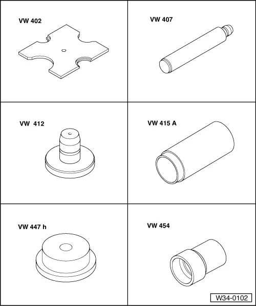
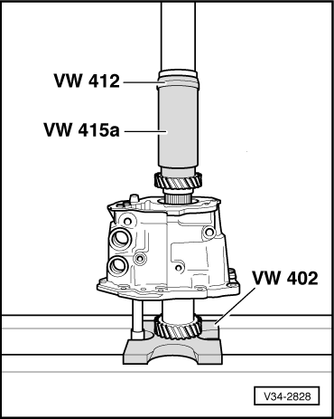
| t | Thrust plate -VW 402- |
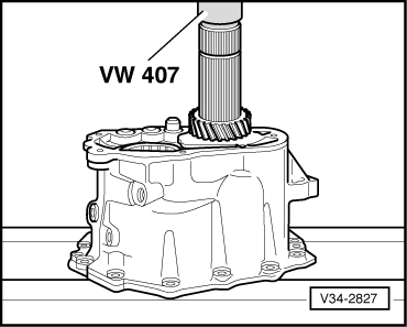
| t | Press tool -VW 407- |
| t | Press tool -VW 412- |
| t | Tube -VW 415 A- |
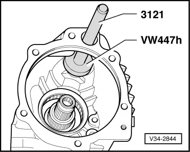
| t | Thrust plate -VW 447 H- |
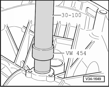
| t | Press tool - VW 454- |
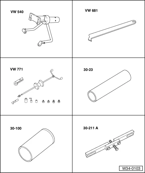
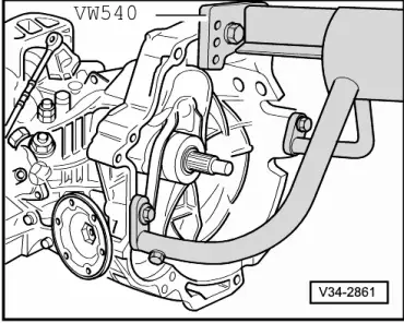
| t | Engine and gearbox support -VW 540- |
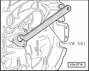
| t | Oil seal extractor lever -VW 681- |
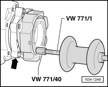
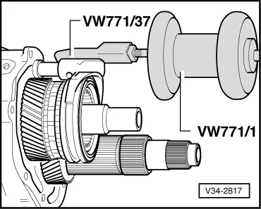
| t | Multi-purpose tool -VW 771- |
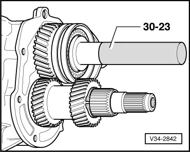
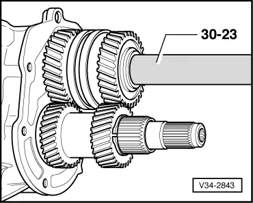
| t | Extension -30-23- |
| t | Drift sleeve -30-100- |
| t | Support bridge -30-211 A- |
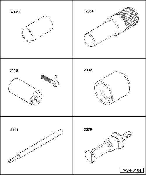
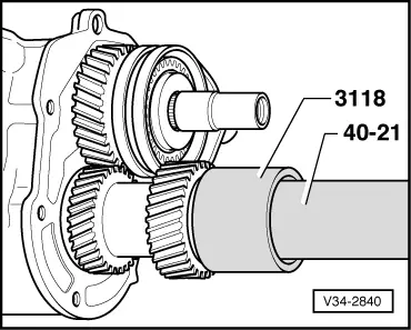
| t | Press tool -40-21- |
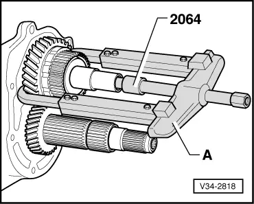
| t | Locking pin -2064- |
| t | Clamping sleeve -3116- |
| t | Press tool -3118- |
| t | Drift -3121- |
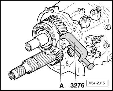
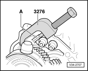
| t | Internal puller -3275- |
|
|
|
|
|
|
|
|
|
|
|
|
 Note
Note |
|
|
|
|
|
|
|
|
|
|
|
|
|
|
|
Note
|
|
|
|
Note
|
|
Note
|
|
|
|
|
|
|
|
|
|
|
|
|
|
|
|
Note
|
|
Note
|
|
|
|
Note
|
|
|
|
 WARNING
|
|
|
|
|
|
|
|
|
|
|
|
|
|
|
|
Note
|
|
|
|
|
|
|
|
|
|
|
|
Note
|
|
Note
|
|
|
|
| Measuring range (mm) | Available shims - Thickness of shims in mm 1) | ||
| 31.01 … 31.11 | 1.05 | ||
| 31.11 … 31.21 | 1.15 | ||
| 31.21 … 31.31 | 1.25 | ||
| 31.31 … 31.41 | 1.35 | ||
| |||
|
|
|
|
|
|
| Available circlips - Thickness in mm 1) | ||||
| 2.32 | 2.40 | 2.48 | ||
| 2.34 | 2.42 | 2.50 | ||
| 2.36 | 2.44 | |||
| 2.38 | 2.46 | |||
| ||||
|
|
|
|
|
Note
|
|
|
|
|
|
|
|
|
|
Note |
|
|
|
|
|
|
|
| Measuring range (mm) | Shims - Thickness of shims in mm 1) | ||
| 7.05 … 7.30 | 1.65 + 1.45 +1.20 | ||
| 7.30 … 7.55 | 1.65 + 1.45 + 0.95 | ||
| 7.55 … 7.80 | 1.65 + 1.45 + 0.70 | ||
| 7.80 … 8.05 | 1.65 + 1.45 +0.45 | ||
| 8.05 … 8.25 | 1.65 + 1.65 | ||
| 8.25 … 8.50 | 1.65 + 1.45 | ||
| 8.50 … 8.75 | 1.65 +1.20 | ||
| 8.75 … 9.00 | 1.65 + 0.95 | ||
| 9.00 … 9.25 | 1.65 + 0.70 | ||
| 9.25 … 9.50 | 1.65 + 0.45 | ||
| |||
|
|
|
|