audi Workshop Repair Guides

Audi Workshop Service and Repair Manuals

Removing gearbox on vehicles with 4-cylinder TDI engine > < Removing and installing gearbox
Removing gearbox on vehicles with 4-cylinder petrol engine
   
Removing gearbox on vehicles with 4-cylinder petrol engine
Special tools and workshop equipment required
t  Support bracket -10-222 A-
t  Gearbox support -3282-
t  Adjustment plate -3282/43-
t  Torque wrench -V.A.G 1331-
t  Torque wrench -V.A.G 1332-
t  Engine and gearbox jack -V.A.G 1383 A-

   
t  Wing compensation plate -T40045-
t  Grease for clutch plate splines -G 000 100-
t  Copper grease (commercially available)
Procedure
  Note
t  All cable ties which are released or cut open during removal must be fitted in the same position when installing.
t  Heat insulation sleeves removed during removal of gearbox must be fitted in the same position when installing.
  Caution
Follow steps required when disconnecting battery → Rep. Gr.27.
  W00-1401
–  With ignition switched off, disconnect battery earth strap -arrow-.
  A27-0098
–  Remove engine cover panel -arrows-.
  A10-10292
–  Detach rubber seal from edges of wing mounting flanges.
–  To avoid damaging edges of wing panels with support bracket -10-222 A-, insert wing compensation plates -T40045- on both sides between the wing mounting flange and the body panel underneath.
  A19-0412
–  Set up support bracket -10-222 A- with adapters -10-222/3- on wing mounting flanges.
–  Engage spindles on engine lifting eyes as illustrated.
–  Take up weight of engine using spindles.
  A34-10016
–  On vehicles fitted with auxiliary heater, remove bolts -arrows- securing exhaust pipe of auxiliary/ additional heater to noise insulation.
  A10-0407
–  Loosen bolts/quick-release fasteners -1- and -2- and remove front noise insulation -A-.
–  If fitted, loosen quick-release fasteners -3- and remove rear noise insulation -B-.
  A34-0530
–  Detach bracket -arrow- for noise insulation.
  N34-0588
–  Unbolt heat shield -arrow- for drive shaft (right-side) from gearbox.
–  Unbolt drive shafts (left and right) from gearbox flange shafts.
  Note
  A34-0521
The flexible pipe connection (de-coupling element) on the front exhaust pipe must not be bent more than 10° – otherwise it can be damaged.
–  Separate the exhaust system at the clamp -arrow- and slide the clamp to rear.
  A26-10015
–  Unscrew bolt -1- and nut -2- and detach retaining bracket for front exhaust pipe.
  A26-10118
Cabriolet:
  Note
On Audi Cabriolet vehicles the following additional steps are required in order to remove the three bottom engine/gearbox bolts:
–  Unbolt torque reaction support -arrows-.
  A34-0531
–  Unscrew nuts -1- on left and right sides, and swivel anti-roll bar -2- downwards.
–  Unscrew nuts -3- on engine mountings (left and right) until bottom of nut is flush with end of stud -arrow-.
–  Use support bracket -10-222 A- to lift engine just enough for nuts -3- to make contact with bottom surface of left and right console for engine mounting.
  A34-0532
Continued for all vehicles:
–  Unscrew the three lower engine/gearbox securing bolts -arrow-.
Cabriolet:
–  Lower engine back down.
  A34-0433
Continued for all vehicles:
–  Unbolt starter from engine/gearbox and secure as necessary → Rep. Gr.27.
  Note
Starter cables do not have to be disconnected.
  N34-0589
–  Drill a hole of 10.2 mm Ø -arrow- in the support elements of gearbox support -3282-.
  A34-0527
–  To remove manual gearbox 01X, set up gearbox support -3282- with adjustment plate -3282/43- and place on engine and gearbox jack -V.A.G 1383 A-.
  Note
t  The support elements-arrows A- and -arrows B- are shown in schematic form on the adjustment plate. The arrow on the adjustment plate points in the direction of travel.
t  Adjustment plate can only be fitted in one correct position.
  A34-0700
–  Align the adjustment plate parallel to the gearbox.
–  Secure support elements to left side of gearbox, as shown in illustration. Tighten bolt (M10 x 20) -arrow on right side- to 20 Nm.
  A34-0701
–  Secure support elements to right side of gearbox, as shown in illustration. Tighten bolt (M10 x 20) -arrow on left side- to 20 Nm.
  A34-0702
–  First remove bolts -1- and then bolts -2-.
  A34-10147
–  Unscrew nuts -arrows- and detach tunnel cross member.
–  Lower gearbox slightly with engine and gearbox jack -V.A.G 1383 A-.
  A37-0448
–  Unplug electrical connector -arrow- for reversing light switch -F4- and move electrical wire clear.
  A34-0666
–  Unscrew connecting rod -2- for selector rod.
–  Unscrew push rod -1-, using an 8 mm hexagon key when unscrewing bolt.
  N34-1208
–  Unscrew nut -arrow- and detach gearbox selector lever from selector shaft.
  A34-10014
–  Remove upper engine/gearbox securing bolts -arrows 1- and -arrows 2-. Please note that retaining brackets for wires/lines and coolant pipe may be secured on bolts -arrows 2- (important for installation).
–  If fitted, remove retaining clips/cable ties together with Lambda probe wiring from gearbox.
  A34-0704
–  Remove remaining engine/gearbox securing bolts -arrow A- and -arrow B-.
–  Press gearbox off dowel sleeves and lower carefully with engine and gearbox jack -V.A.G 1383 A- just far enough to gain access to clutch slave cylinder.
  Note
When lowering gearbox, ensure hydraulic pipe/hose to slave cylinder is not damaged.
  A34-0434
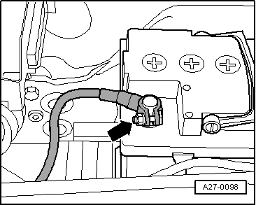
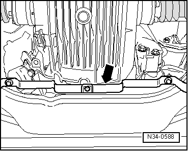
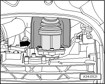
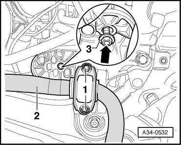
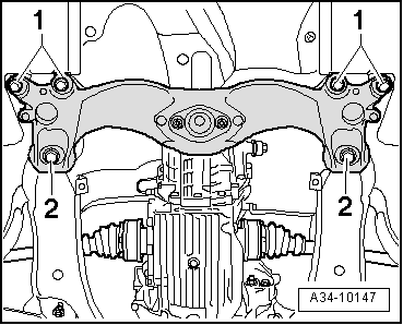
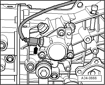
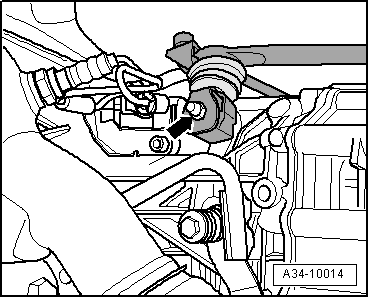
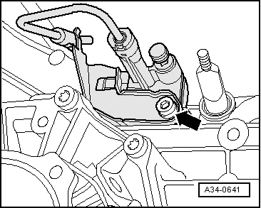
–  Remove clutch slave cylinder from gearbox -arrow- and secure with wire, do not open pipe/hose system.
  Caution
Do not depress clutch pedal after removing clutch slave cylinder. The slave cylinder would then be destroyed once pedal force exceeds approx. 300 N.
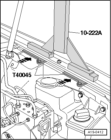
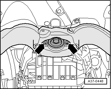
–  Lower gearbox completely with engine and gearbox jack -V.A.G 1383 A-.
  Note
t  
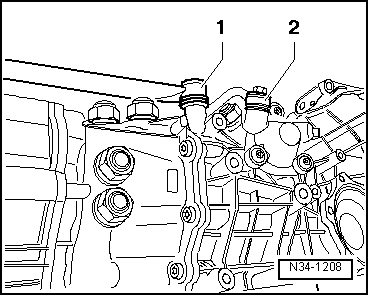
Make sure that all wiring has been detached from top of gearbox.
t  When lowering gearbox, make sure there is sufficient clearance from drive shafts.
–  Before carrying out assembly work, secure gearbox to assembly stand, using engine and gearbox support -VW 540- → Chapter.
  A34-0641
–  If you will be installing a new gearbox instead of the one removed, the gearbox mounting has to be transferred to the new gearbox -arrows- → Anchor.
Installing gearbox → Chapter
  A34-0703

Removing gearbox on vehicles with 4-cylinder TDI engine > < Removing and installing gearbox