audi Workshop Repair Guides

Audi Workshop Service and Repair Manuals

Exploded view - dismantling and assembling centre differential housing > < Exploded view - removing and installing input shaft, pinion shaft, hollow shaft, reverse gear wheel and reverse selector gear
Assembly sequence - dismantling and assembling gearbox
Removing and installing ball bearing for input shaft, end cover, centre differential, gearbox cover, selector shaft and bearing housing with input shaft and pinion shaft/hollow shaft.
   
Special tools and workshop equipment required
t  Drift sleeve -VW 244 B-
t  Thrust plate -VW 401-
t  Thrust plate -VW 402-
t  Press tool -VW 412-
t  Tube -VW 415 A-
t  Press tool -VW 433-

   
t  Tube -VW 519-
t  Engine and gearbox support -VW 540-
t  Extension -30 - 23-
t  Drift sleeve -40 - 21-
t  Support -40 - 103-
t  Thrust plate -40 - 105-

   
t  Drift sleeve -41 - 501-
t  Gearbox bracket -2004-
t  Locking pin -2064-
t  Thrust piece -3002-
t  Door hinge alignment tool (M8 and M10) -3114/2-
t  Fitting tool -T10246-

   
t  Workshop press -V.A.G 1290 A-
t  Drip tray -V.A.G 1306-
t  Torque wrench -V.A.G 1331-
t  Torque wrench -V.A.G 1332-
t  Tapered roller bearing puller -V.A.G 1582-
t  -1-Internal puller -Kukko 21/2-
t  -2-Puller -Kukko 18/2-

   
t  Plate -T40086-
t  Plate -T40088/1-
t  Sleeve -T40088/2-
t  Adapter -V.A.G 1582/12-
t  -1-Two-arm puller -Kukko 20/10-
t  -2-Puller hook, length 200 mm
t  -2-Puller hook, length 250 mm

   
t  Hot air blower -V.A.G 1416-
  W00-0004
t  Inductive heater -VAS 6414-
t  Feeler gauge
t  2 bolts M8 (length 70 mm) with washers
t  Sealing paste -AMV 188 001 02-
t  Assembly sleeve -01E 311 120-
t  Locking fluid -AMV 185 101 A1-
  W00-10814
–  Secure gearbox to support clamp -VW 313- or engine and gearbox support -VAS 6095- → Chapter.
–  Place drip tray -V.A.G 1306- or similar under gearbox.
–  Drain gear oil.
  A34-10101
–  Remove clutch release lever -A- together with release bearing.
–  Remove guide sleeve -B-
–  Remove dished spring -C-.
–  Then remove circlip -D- in front of ball bearing for input shaft.
–  If the input shaft or gearbox housing is not to be renewed, note the thickness of the circlip.
  V30-0375
–  Pull the ball bearing for input shaft out of gearbox housing.
  A34-10051
–  Remove the circlip -arrow- behind the ball bearing for input shaft.
–  If the input shaft or gearbox housing is not to be renewed, note the thickness of the circlip.
  V35-1238
–  Unscrew bolts -arrows- and detach centre differential housing -A-.
  Note
The illustration shows only 4 of the 6 securing bolts.
–  Remove centre differential and spring from pinion shaft/hollow shaft.
  A34-0707
–  Remove bolts -arrows- and take off selector shaft cover -A-.
  A34-0715
–  Unscrew the two locking bolts -1- for selector shaft.
l  Make sure that no gear has been engaged.
–  Push selector shaft -2- into gearbox as far as it will go, simultaneously removing pin -3-.
–  Pull out selector shaft.
  A34-0716
–  Move two selector rods -arrow A- and -arrow B- to lock input shaft by selecting two gears (e.g. reverse gear and 1st gear).
  A34-10054
–  Unscrew bolts securing gearbox cover -A- and bolts securing bearing housing -B- to gearbox housing -C-.
–  Carefully pull gearbox cover towards rear and off. The bearing housing remains fitted to the gearbox housing.
  Note
Always renew O-ring -arrow- on gearbox cover.
  A34-10052
–  Secure bearing housing to gearbox housing -arrows- with two bolts M8 (length approx. 70 mm) and washers.
–  Tighten the two bolts to max. 10 Nm.
–  Detach oil collector -A-.
  A34-10053
–  Unscrew multi-point socket head bolt -1- for input shaft.
  A34-10055
–  Detach 6th speed selector gear with inner race for roller bearing and thrust washer.
A - Two-arm puller, e.g. -Kukko 20/10-
  Note
Check the gear teeth on the selector gears and gear wheels for damage after pulling them off.
–  Remove synchro-ring and needle bearing for 6th speed selector gear.
  A34-10056
–  Pull off 6th gear wheel.
A - Two-arm puller, e.g. -Kukko 20/10- with 200 mm hooks
–  Remove spacer sleeve from hollow shaft.
  A34-10057
–  Pull out pin with clip -A- for securing selector fork for 5th and 6th gear from selector rod -B-.
l  Mark installation position of locking collar in relation to synchro-hub -arrow-.
–  Move selector fork -C- downwards and detach with locking collar -D-.
  A34-10058
–  Heat synchro-hub for 5th and 6th gear -arrow- to approx. 100 °C using hot air blower -V.A.G 1416-.
–  Pull off 5th speed selector gear together with needle bearing inner race for 6th gear and synchro-hub for 5th and 6th gear.
A - Two-arm puller, e.g. -Kukko 20/10- with 200 mm hooks
  Note
t  Counter-hold two-arm puller using e.g. open end spanner -B-.
t  If the needle bearing inner race for 6th gear is in contact with press tool -VW 433-, insert locking pin -2064- into hole in input shaft to pull off the components all the way.
  A34-10380
–  Pull off 5th gear wheel.
A - Two-arm puller, e.g. -Kukko 20/10- with 250 mm hooks
  Note
The 5th gear wheel can also be pulled off together with the 4th gear wheel → Anchor.
  A34-10060
–  Pull off 4th gear wheel.
A - Puller, e.g. -Kukko 18/2-
  Note
Counter-hold puller-A- using e.g. gearbox bracket -2004-.
  A34-10062
–  Pull off 4th speed selector gear with needle bearing inner race for 5th gear and thrust washer.
  Caution
Risk of damage to dog teeth on 4th speed selector gear.
Hooks of two-arm puller must not come into contact with dog teeth of 4th speed selector gear during removal.
A - Two-arm puller, e.g. -Kukko 20/10- with 200 mm hooks
–  Counter-hold two-arm puller using e.g. open end spanner -B-.
–  Remove synchro-ring and needle bearing for 4th speed selector gear.
  A34-10061
–  If fitted, remove lock washer -A- from selector rod for 3rd and 4th gear, using side-cutting pliers or similar.
–  Remove spring -B-.
  A34-10855
–  Pull pin with clip -A- securing selector fork for 3rd and 4th gear out from selector rod -B-.
l  Mark installation position of locking collar in relation to synchro-hub -arrow-.
–  Detach selector fork -C- with locking collar -D-.
–  Remove circlip for 3rd gear and 4th gear synchro-hub and note thickness of circlip.
  A34-10063
Pull off 3rd speed selector gear with synchro-hub for 3rd and 4th gear.
A - Puller, e.g. -Kukko 18/2-
  Note
Counter-hold puller-A- using e.g. gearbox bracket -2004- to prevent plate -T40086- from making contact with 3rd gear wheel or selector rod for 5th and 6th gear.
–  Remove circlip for 3rd speed selector gear needle bearing and detach 3rd gear needle bearing.
  A34-10064
–  Pull off thrust washer -B- for 3rd speed selector gear.
A - Two-arm puller, e.g. -Kukko 20/10- with 250 mm hooks
  A34-10065
–  Unscrew bolts -arrows- for reverse shaft support.
–  Prevent pinion shaft from falling out and secure onto hollow shaft using e.g. a hose clip -A-.
–  Unscrew the two bolts -B- securing bearing housing to gearbox housing and detach bearing housing.
–  Remove hose clip from pinion shaft.
  A34-10066
–  Detach needle bearing -A- for pinion shaft -B- and pull out pinion shaft from hollow shaft -C-.
  A34-10067
–  Insert an internal puller-A- e.g. -Kukko 21/2- into bore for reverse shaft support.
–  Spread open internal puller far enough for it to make contact with reverse shaft support -B-.
–  Drive reverse shaft support carefully out of bearing housing -direction of arrow- and remove with reverse gear wheel.
  A34-10068
–  Remove circlip for 3rd gear wheel and note thickness of circlip.
–  Pull off 3rd gear wheel.
A - Two-arm puller, e.g. -Kukko 20/10- with 250 mm hooks
  A34-10070
–  Now pull out input shaft -A- carefully from bearing housing at an angle from the front -direction of arrow-.
  A34-10069
–  Pull pin with clip -A- for securing selector fork for reverse gear out from selector rod -B-.
l  Mark installation position of locking collar in relation to synchro-hub -arrow-.
–  Detach selector fork -C- with locking collar -D-.
  A34-10071
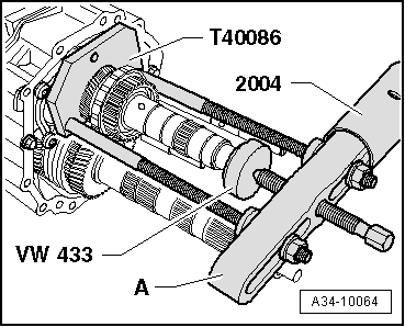
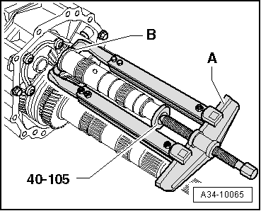
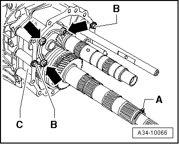
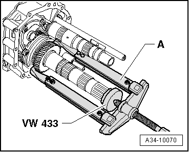
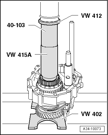
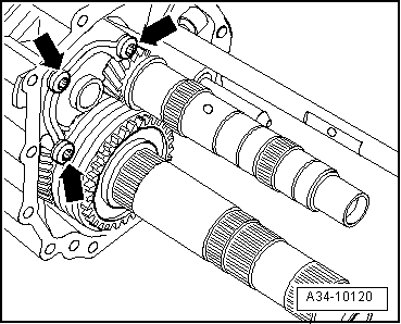
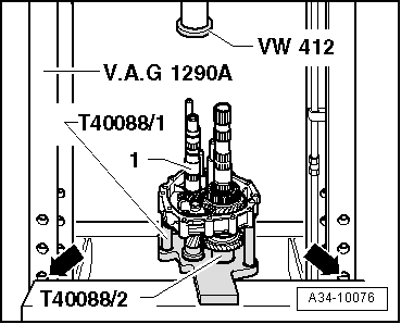
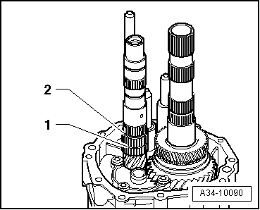
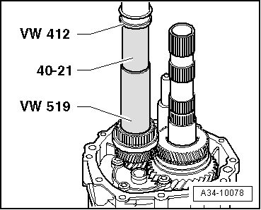
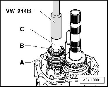
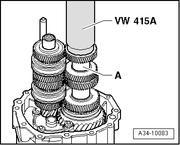
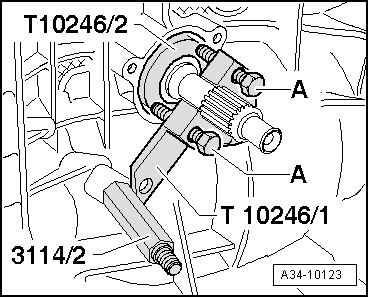
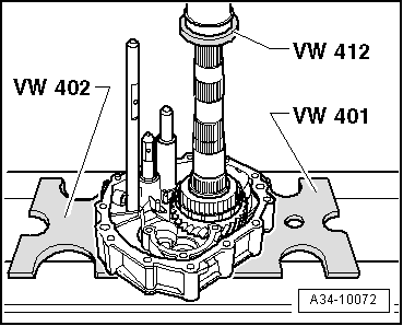
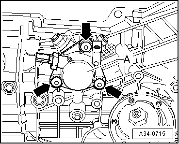
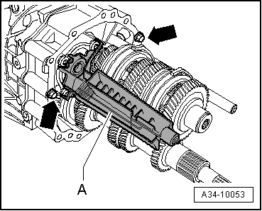
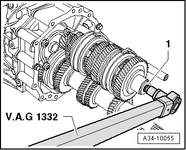
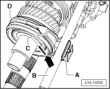
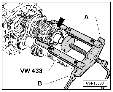
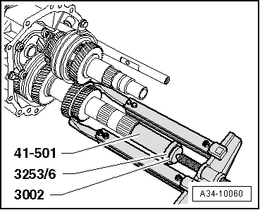
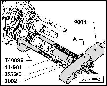
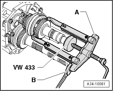
–  Press off synchro-hub for reverse gear from hollow shaft.
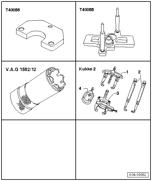
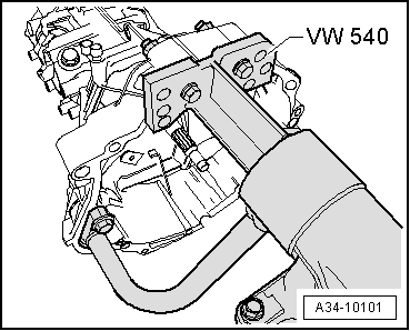
  Note
Place the bearing housing onto thrust plates -VW 401- and -VW 402- so that the hollow shaft and selector rods are not damaged when pressing off the synchro-hub.
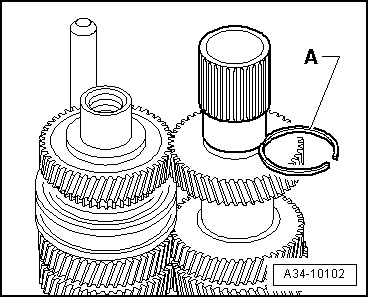
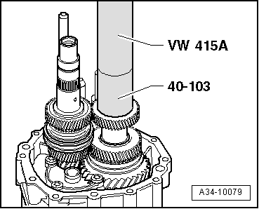
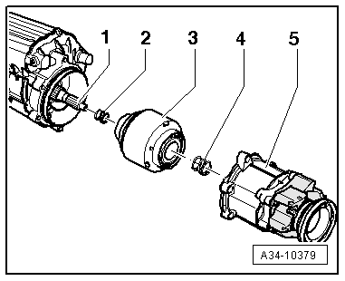
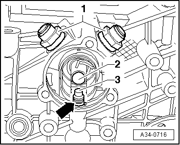
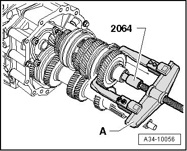
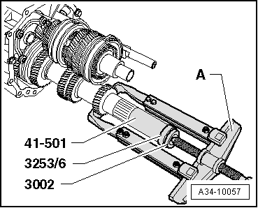
–  Detach reverse selector gear, needle bearing for reverse selector gear and reverse gear synchro-hub.
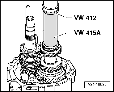
–  Guide hollow shaft out of selector fork for 1st and 2nd gear and bearing housing.
Assembling gearbox
l  If the input shaft or the gearbox housing have been renewed, you must first re-determine the thickness of the input shaft circlips → Chapter „Adjusting input shaft“.
  Note
t  Lubricate all needle bearings with gear oil before fitting.
t  Checking synchro-rings for wear → Fig..
t  
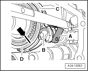
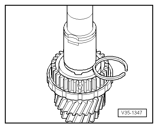
Inserting spring in selector gear → Fig..
t  Heat gear wheels, needle bearing inner races and synchro-hubs to approx. 100 °C (max.) before pressing on (wear protective gloves).
t  
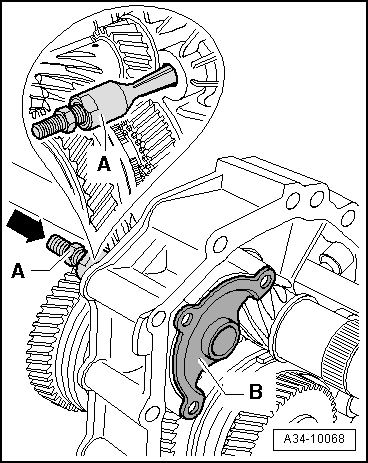
The thread must be cleaned if a micro-encapsulated multi-point socket head bolt was previously fitted in the threaded hole of the input shaft.
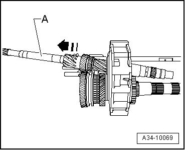
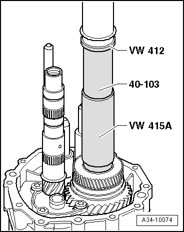
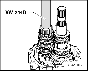
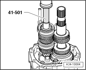
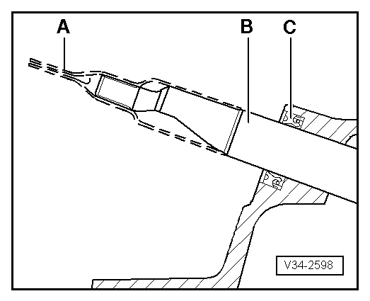
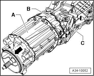
–  Insert hollow shaft in bearing housing and selector fork for 1st and 2nd gear.
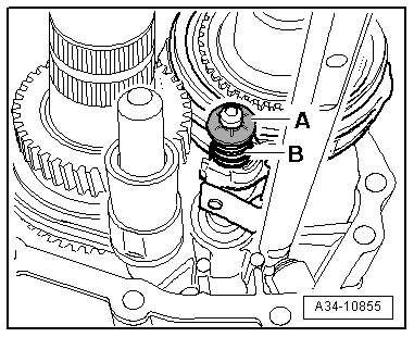
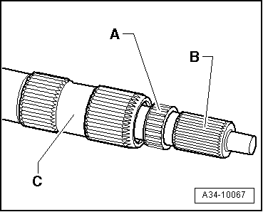
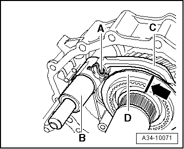
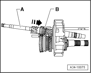
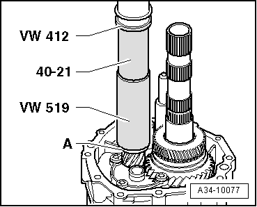
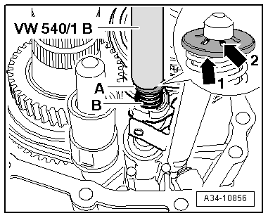
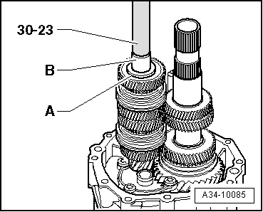
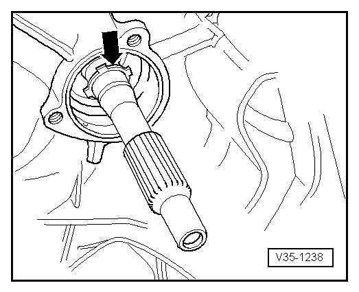
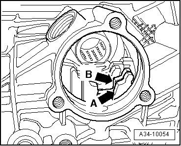
–  Place reverse gear selector gear with needle bearing, spring and synchro-ring onto hollow shaft.
l  The lugs on the synchro-ring should engage into the recesses in the selector gear.
  A34-10072
–  Press on reverse gear synchro-hub.
l  Installation position: high inside collar faces 3rd gear wheel.
–  Check axial clearance of reverse selector gear.
  A34-10073
–  Now insert input shaft -A- with needle roller bearing -B- into bearing housing in -direction of arrow- at an angle towards the rear.
  A34-10075
–  Install reverse gear wheel and tighten 3 bolts -arrows- for reverse shaft support to 30 Nm.
Exploded view - reverse gear wheel → Fig.
  A34-10120
–  Slide reverse gear selector fork -C- together with locking collar -D- onto selector rod -B- and reverse gear synchro-hub.
l  The markings on locking collar and synchro-hub -arrow- must coincide.
l  The chamfer on the locking collar faces the reverse selector gear.
–  If the bores of selector fork and selector rod coincide, clip in pin with clip -A-.
  A34-10071
–  Align work table of workshop press -V.A.G 1290 A- so that the 3rd bore -arrow- is visible above the work surface.
–  Place holding plate -T40088/1- with sleeve -T40088/2- onto work table.
–  Insert bearing housing with shafts and selector rods into holding plate -T40088/1-.
The distance between input shaft -1- and press tool -VW 412- should be approx. 210 mm, so that it is possible to perform the following work steps without changing the position of the work table.
  A34-10076
–  Press on 3rd gear wheel.
l  Installation position: machined side faces reverse gear synchro-hub.
–  Insert circlip for 3rd gear wheel.
l  When renewing gear wheel or hollow shaft:
Re-determine thickness of circlip for 3rd gear wheel:
–  Determine the thickest circlip that will just fit and install it. For part number refer to → Electronic parts catalogue.
The following circlips are available:
  A34-10074
Circlip thickness (mm)
1.901.982.06
1.942.022.10

   
–  Press on thrust washer -A- for 3rd speed selector gear until limit stop.
  A34-10077
–  Fit needle bearing for 3rd speed selector gear -1- and circlip -2- for 3rd gear needle bearing onto input shaft.
–  Then fit 3rd speed selector gear with spring and synchro-ring.
l  The lugs on the synchro-ring should engage into the recesses in the selector gear.
  A34-10090
–  Press on heated synchro-hub for 3rd and 4th gear
l  Installation position: high inside collar faces 3rd speed selector gear.
  A34-10078
–  Insert circlip for synchro-hub for 3rd and 4th gear.
l  When renewing synchro-hub or input shaft:
Re-determine thickness of circlip for synchro-hub for 3rd and 4th gear:
–  Determine the thickest circlip that will just fit and install it. For part number refer to → Electronic parts catalogue.
The following circlips are available:
  V35-1347
Circlip thickness (mm)
1.901.962.02
1.931.992.05

–  Check axial clearance of 3rd speed selector gear.
   
–  Slide selector fork for 3rd and 4th gear -C- together with locking collar -D- onto selector rod -B- and synchro-hub for 3rd and 4th gear.
l  The markings on locking collar and synchro-hub -arrow- must coincide.
–  If the bores of selector fork and selector rod coincide, clip in pin with clip -A-.
  Note
Do not insert pin with clip for 5th/6th gear selector fork (Ø 6 mm) into selector fork for 3rd and 4th gear.
  A34-10063
–  If previously fitted, install spring -B- on selector rod for 3rd and 4th gear and drive on lock washer -A-.
l  Engage 3rd gear before driving on lock washer -A-.
l  Installation position of lock washer: collar -arrow 1- faces spring -B-.
l  Lock washer must engage below shoulder -arrow 2- on selector rod.
  Note
Different versions are fitted - either with or without spring on selector rod for 3rd and 4th gear.
  A34-10856
–  Fit 4th speed selector gear -A- with spring, synchro-ring, needle bearing and thrust washer for 3rd and 4th gear -B-.
–  Press on heated inner race -C- for needle bearing for 5th speed selector gear.
–  Check axial clearance of 4th speed selector gear.
  A34-10081
–  Heat 4th gear wheel and press on.
l  Installation position: high inside collar faces 5th gear wheel.
  A34-10079
–  Heat 5th gear wheel and press on.
l  Installation position: high inside collar faces 4th gear.
–  Place 5th speed selector gear with spring, synchro-ring and needle bearing onto input shaft.
l  The lugs on the synchro-ring should engage into the recesses in the selector gear.
  A34-10080
–  Fit and press on heated synchro-hub for 5th and 6th gear.
–  Check axial clearance of 5th speed selector gear.
  A34-10082
–  Slide selector fork for 5th and 6th gear -C- together with locking collar -D- onto synchro-hub for 5th and 6th gear.
l  The markings on locking collar and synchro-hub -arrow- must coincide.
–  Move selector fork for 5th and 6th gear -C- into selector rod -B-.
–  If the bores of selector fork and selector rod coincide, clip in pin with clip -A-.
  A34-10058
–  Press on heated inner race for needle bearing for 5th speed selector gear.
  A34-10084
–  Fit 6th speed selector gear with spring, synchro-ring, needle bearing and thrust washer for 6th gear -A-.
–  Heat inner race -B- for needle roller bearing and press on.
–  Check axial clearance of 6th speed selector gear.
  A34-10085
–  Fit spacer sleeve -A- onto hollow shaft.
–  Heat 6th gear wheel and press on.
  A34-10083
Insert circlip -A- for 6th gear wheel.
l  When renewing gear wheel or hollow shaft:
Re-determine circlip -A- for 6th gear wheel:
–  Determine the thickest circlip that will just fit and install it. For part number refer to → Electronic parts catalogue.
The following circlips are available:
  A34-10102
Circlip thickness (mm)
1.902.022.14
1.932.052.17
1.962.082.20
1.992.11 

–  Take out bearing housing from plate -T40088/1-.
   
–  Push pinion shaft -B- with large needle bearing into hollow shaft -C- and fit small needle bearing -A-.
–  Prevent pinion shaft from falling out and secure on hollow shaft using e.g. a hose clip → Anchor.
  A34-10067
–  Secure bearing housing to gearbox housing with two bolts M8 (length approx. 70 mm) -arrows- and washers.
–  Tighten the two bolts to max. 10 Nm.
  Note
Do not install oil collector -A- at this stage.
  A34-10053
–  Move two selector rods -arrow A- and -arrow B- to lock input shaft by selecting two gears (e.g. reverse gear and 1st gear).
  A34-10054
–  Tighten new multi-point socket head bolt -1- for input shaft to 200 Nm.
–  Then remove the complete bearing housing from the gearbox housing.
–  Check that the two dowel sleeves for centralising the bearing housing are fitted in the gearbox housing.
–  Apply sealing paste -AMV 188 001 02- evenly and not too thickly onto contact surfaces between gearbox housing and bearing housing.
–  Fit bearing housing onto gearbox housing.
  A34-10055
–  Clip oil collector -A- into reverse shaft support.
  Note
Make sure that the bolts -arrows- are removed.
–  Remove hose clip from pinion shaft → Anchor.
–  Check that the two dowel sleeves for centralising the gearbox cover are fitted in the bearing housing.
–  Apply sealing paste -AMV 188 001 02- evenly and not too thickly onto contact surfaces between bearing housing and gearbox cover.
  A34-10053
–  Tighten securing bolts for gearbox cover -A- and bearing housing -B- to gearbox housing -C- to 35 Nm + 90° further.
–  Fit new O-ring -arrow- and lubricate lightly with gear oil.
  A34-10052
–  Place small spring -2- and centre differential -3- onto pinion shaft/hollow shaft -1-.
–  Insert large spring -4-.
–  Then fit centre differential housing -5- onto gearbox cover.
  A34-10379
–  Tighten bolts -arrows-. Tightening torque → Item
  Note
The illustration shows only 4 of the 6 bolts.
  A34-0707
–  Push assembly sleeve -01E 311 120--A- onto selector shaft -B-.
  Note
To avoid damaging oil seal -C-, always use assembly sleeve -01E 311 120--A- when installing oil seal and selector shaft.
–  Move selector rods to neutral.
–  Install complete selector shaft.
t  Installation position: Chamfer of selector shaft points downwards.
  V34-2598
–  Push selector shaft -2- into gearbox as far as it will go, simultaneously inserting pin -3-.
l  Installation position for pin -3-: groove -arrow- on pin points towards selector shaft cover.
–  Clean threads of locking bolt -1- with a wire brush. Then insert bolts with locking fluid -AMV 185 101 A1- and tighten to 45 Nm.
  A34-0716
–  Fit cover -A- with new O-ring.
–  Clean threads of bolts -arrows- with a wire brush. Then insert bolts with locking fluid -AMV 185 101 A1- and tighten to 24 Nm.
  A34-0715
–  Fit rear circlip -arrow- for input shaft ball bearing.
–  Then push ball bearing onto input shaft.
Installation position:
The closed side of the ball cage faces the gearbox housing.
  V35-1238
–  Pressing in ball bearing:
First screw door hinge alignment tool (M8 and M10) -3114/2- into tapped hole for ball-head pin.
Slide the thrust plate -T10246/2- onto input shaft.
Now position fitting tool -T10246/1- behind splines for clutch plate. Tighten bolts -A- only slightly. The bolts locate in the recesses in the thrust plate -T10246/2-.
Press in ball bearing onto stop by tightening bolts -A- alternately (1/2 turn at a time).
  A34-10123
–  Now fit front circlip -D- for input shaft ball bearing.
–  Then fit dished spring -C-.
Installation position:
The convex side faces guide sleeve -B-.
–  Fit a shrink hose onto input shaft splines.
–  Fit guide sleeve -B- for release bearing → Chapter.
–  Remove shrink hose.
–  Fit clutch release lever -A- with release bearing → Chapter.
–  Select all gears.
  V30-0375

Exploded view - dismantling and assembling centre differential housing > < Exploded view - removing and installing input shaft, pinion shaft, hollow shaft, reverse gear wheel and reverse selector gear