audi Workshop Repair Guides

Audi Workshop Service and Repair Manuals

Installing gearbox on vehicles with 4-cylinder or 6-cylinder engine > < Removing gearbox on vehicles with 4-cylinder engine
Removing gearbox on vehicles with 6-cylinder engine
   
Removing gearbox on vehicles with 6-cylinder engine
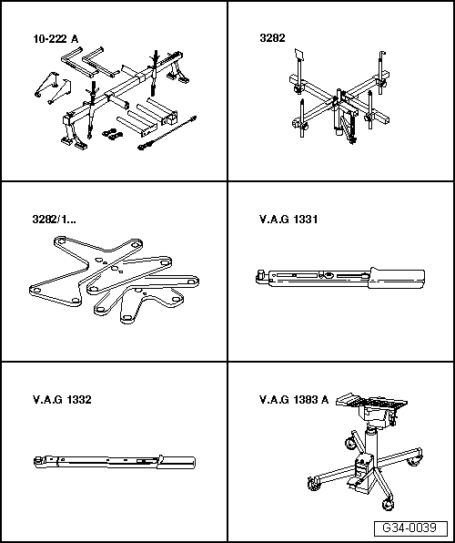
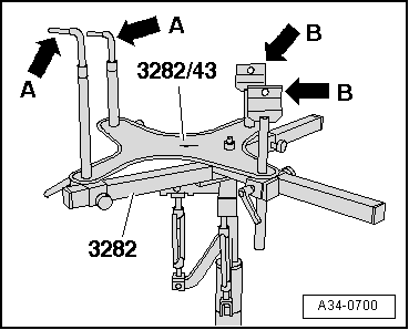
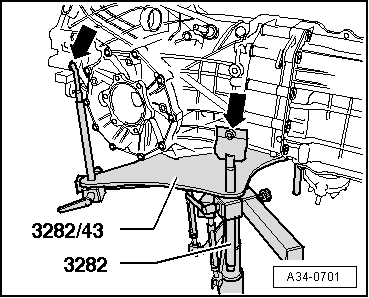
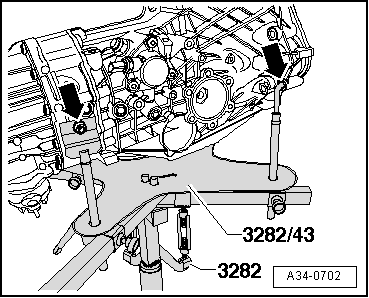
Special tools and workshop equipment required
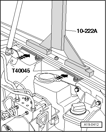
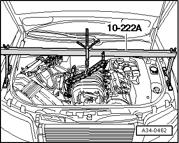
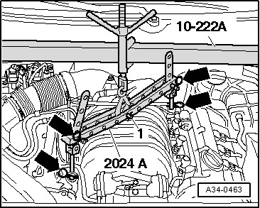
t  Support bracket -10 - 222 A-
t  Gearbox support -3282-
t  Adjustment plate -3282/43-
t  Torque wrench -V.A.G 1331-
t  Torque wrench -V.A.G 1332-
t  Engine and gearbox jack -V.A.G 1383 A-

   
t  Wing compensation plate -T40045-
  W00-1401
t  Lifting tackle -2024 A-
t  Grease for clutch plate splines -G 000 100-
t  Copper grease (commercially available)
t  2 bolts (M10 x 20)
  Note
t  All cable ties which are released or cut open during removal must be fitted in the same position when installing.
t  Heat insulation sleeves removed during removal of gearbox must be fitted in the same position when installing.
  Caution
Follow steps required when disconnecting battery → Electrical system; Rep. gr.27.
  W00-0224
–  With ignition switched off, disconnect battery earth strap -arrow-.
  A27-0098
–  Pull off rear engine cover -arrows-.
  A10-1032
–  Pull off front engine cover -arrows-.
  A10-1004
–  Remove cover -1- on left side of engine compartment.
  A10-1031
–  Unbolt coolant expansion tank -arrow-.
–  Disconnect electrical wiring for coolant shortage indicator switch -F 66- at bottom of coolant expansion tank.
–  Tie coolant expansion tank to one side, leaving coolant hoses -1-, -2- and -3- connected.
  A10-0989
–  Remove cover -1- on right side of engine compartment.
  A10-1030
–  Remove bolts -arrows- from solenoid valve mounting plate -3-.
–  Detach air intake hose -1- from air-mass meter -G70-.
–  Pull hose -4- for crankcase breather system off air duct -2-.
  A34-0460
–  Unscrew bolt -arrow- and disconnect air duct -2- from throttle valve module -J338-.
–  If fitted, detach hose -1- from air duct.
  Note
In the illustration, the air duct is shown from the rear and with the engine removed.
–  Unscrew engine/gearbox securing bolts which are accessible from above.
  A34-0461
–  Detach connectors -1 ... 4- from retainer at left side of bulkhead.
–  Unplug electrical connectors -1- and -4-.
–  Move Lambda probe wiring clear.
–  Remove retainer for connectors.
  A10-1002
–  Unscrew nut -2- (access from above), connecting left front exhaust pipe with exhaust manifold.
  Note
t  For illustration purposes here shown with engine removed.
t  The nuts -1- and -3- (accessible from below) are removed at a later stage.
  A26-0439
–  Detach rubber seal from edges of wing mounting flanges.
–  To avoid damaging edges of wing panels with support bracket -10-222 A-, insert wing compensation plates -T40045- on both sides between the wing mounting flange and the body panel underneath.
  A19-0412
–  Set up support bracket -10 - 222 A- on wing mounting flanges.
  A34-0462
–  Remove eye of lifting tackle -2024 A-.
–  Re-insert pin -1- in middle hole on lifting tackle and secure it with split pin.
–  Hook pin on lifting tackle -2024 A- onto spindle on support bracket -10 - 222 A-.
–  Hook lifting tackle -2024 A- into lifting eyes at front and rear of engine.
  WARNING
Support hooks and locking pins on lifting tackle must be secured with retainers -arrows- in illustration.
–  Slightly pretension engine with spindle of support bracket.
  A34-0463
–  On vehicles fitted with auxiliary heater, remove bolts -arrows- securing exhaust pipe of auxiliary/ additional heater to noise insulation.
  A10-0407
–  Loosen bolts/quick-release fasteners -1- and -2- and remove front noise insulation -A-.
–  If fitted, loosen quick-release fasteners -3- and remove rear noise insulation -B-.
  A34-0530
–  Detach bracket -arrows- for noise insulation.
  A10-0968
–  Remove heat shield -arrow- for drive shafts (left and right).
–  Detach drive shafts from flange shafts, lift clear and secure.
  Note
Make sure you do not damage surface coating on drive shafts.
  A34-0521
–  If fitted, remove tunnel cross member (front) -1 … 4-.
  A26-0568
–  Disconnect exhaust system at clamps -arrows-.
–  Remove front exhaust pipe with catalytic converter (left-side) → Engine, mechanics; Rep. gr.26.
–  Remove bracket for front exhaust pipe (right-side) from gearbox.
  A26-0535
–  If fitted, unscrew heat shield for propshaft -arrows-.
  V39-1844
–  Remove bolts -arrows- at gearbox/propshaft flange.
–  Slide propshaft together towards rear final drive. The constant velocity joints can be moved axially.
–  Tie propshaft to side.
  A34-10146
–  Unscrew nuts -1- at bottom of engine mountings (left and right).
  A10-0088
–  If fitted, unclip operating rod for vehicle level sender -G78- from lower transverse link -arrow-.
  A17-0147
–  Before loosening the subframe, use locating pins -3393- to check whether holes -1- and -2- are aligned.
If this is not the case, wheel alignment has to be checked after installing the subframe.
  A40-0125
–  First remove front bolts -2- and -3- on subframe (left and right). Then remove bolts -1-.
–  Lower subframe at the front.
  A15-0220
–  Unscrew bottom engine/gearbox securing bolts -arrows-.
  A34-0433
–  Temporarily secure subframe again.
Temporary tightening torque:
1 - approx. 100 Nm
2 - approx. 70 Nm
3 - approx. 70 Nm
  Caution
Do not renew bolts yet or tighten to their final torque. This will be done when installing the gearbox.
  A15-0220
–  Unscrew connecting rod -2- for selector rod.
–  Detach push rod -1-; to do so, unscrew hexagon socket head bolt.
  N34-1208
–  Unplug electrical connector -arrow- for reversing light switch -F4- and move electrical wire clear.
  A34-0666
–  Unscrew nut -arrow- and detach gearbox selector lever from selector shaft.
  A34-10014
–  If fitted, remove engine speed sender -G28- from left side of gearbox -arrow- and lay aside.
  A34-0119
–  Detach starter from engine/gearbox and secure if necessary → Electrical system; Rep. gr.27.
  Note
Starter cables do not have to be disconnected.
  N34-0589
–  If not already provided, drill a hole of 10.2 mm Ø -arrow- in the support elements of gearbox support -3282-.
  A34-0527
–  To remove manual gearbox 02X (four-wheel drive) set up gearbox support -3282- with adjustment plate -3282 /43- and place on engine and gearbox jack -V.A.G 1383 A-.
  Note
t  The support elements-arrows A- and -arrows B- are shown in schematic form on the adjustment plate. The arrow on the adjustment plate points in the direction of travel.
t  Adjustment plate can only be fitted in one correct position.
  A34-0700
–  Align the adjustment plate parallel to the gearbox.
–  Secure support elements to left side of gearbox, as shown in illustration. Tighten bolt (M10 x 20) -arrow on right side- to 20 Nm.
  A34-0701
–  Secure support elements to right side of gearbox, as shown in illustration. Tighten bolt (M10 x 20) -arrow on left side- to 20 Nm.
  A34-0702
–  First remove bolts -1- and then bolts -2- at tunnel cross member.
  A34-10147
–  Unscrew nuts -arrows- and detach tunnel cross member.
  A37-0448
–  Remove remaining engine/gearbox securing bolts -arrow A- and -arrow B-.
–  Press gearbox off dowel sleeves and lower carefully with engine and gearbox jack -V.A.G 1383 A- just far enough to gain access to the clutch slave cylinder.
  Note
When lowering gearbox, ensure hydraulic line to clutch slave cylinder is not damaged.
  A34-0434
–  Detach clutch slave cylinder from gearbox -arrow- and secure with wire; do not open pipe/hose system.
  Caution
Do not depress clutch pedal after removing slave cylinder. The slave cylinder would then be destroyed once pedal force exceeds approx. 300 N.
  A34-0641
–  If fitted, open cable ties -arrow A- and -arrow B-, unclip Lambda probe wires at the side -arrows C- and move wires clear.
–  Lower gearbox.
  Note
When lowering gearbox, make sure there is sufficient clearance from drive shafts.
–  Before carrying out assembly work, secure gearbox to assembly stand or engine and gearbox support -VAS 6095-, using engine and gearbox support -VW 540- → Chapter.
  A34-10003
–  If you will be installing a new gearbox instead of the one removed, the gearbox mounting has to be transferred to the new gearbox -arrows- → Chapter.
Installing gearbox → Chapter
  A34-0703

Installing gearbox on vehicles with 4-cylinder or 6-cylinder engine > < Removing gearbox on vehicles with 4-cylinder engine