
A4 Mk2
| Exploded view - servicing clutch release mechanism |
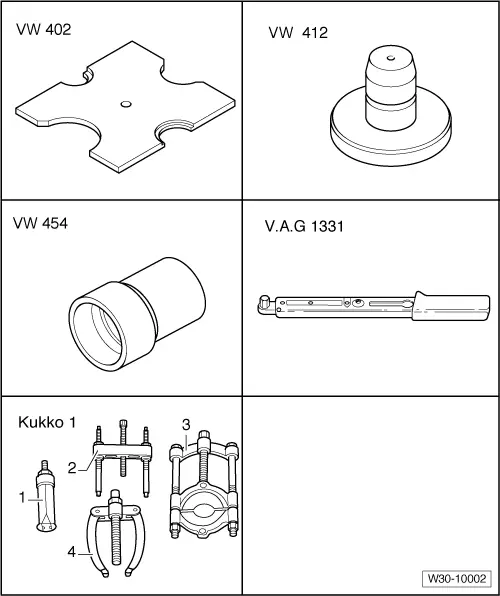
| Special tools and workshop equipment required |
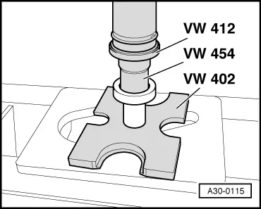
| t | Thrust plate -VW 402- |
| t | Press tool -VW 412- |
| t | Press tool -VW 454- |
| t | Torque wrench -V.A.G 1331- |
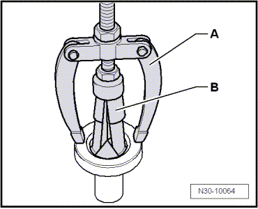
| t | -1-Internal puller -Kukko 21/5- |
| t | -4-Counter-support -Kukko 22/1- |
| t | Sealing grease -G 052 128 A1- |
| t | Adhesive -AMV 195 KD1 01- |
| t | Copper grease (commercially available) |
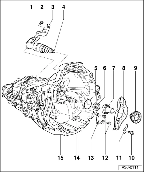
| 1 - | Clutch slave cylinder |
| q | Removing and installing → Chapter |
| q | Do not operate clutch pedal after slave cylinder has been removed |
| q | When installing, push in until the securing bolt → Item can be fitted |
| q | Bleeding clutch system → Chapter |
| q | Tighten bleeder valve to 4.5 Nm |
| 2 - | Hexagon socket head bolt |
| q | 23 Nm |
| q | Clutch slave cylinder to gearbox |
| q | Self-locking |
| q | Always renew |
| 3 - | Bracket |
| q | For pipe/hose assembly |
| q | Bolt to gearbox with clutch slave cylinder |
| 4 - | Plunger |
| q | Lubricate end of plunger with copper grease (commercially available) |
| 5 - | O-ring |
| q | Always renew → Fig. |
| q | Lubricate with gear oil before installing |
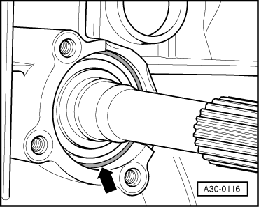
| 6 - | Oil seal |
| q | For input shaft |
| q | Pull out of guide sleeve → Item → Fig.. |
| q | Installation depth → Fig. |
| q | Press into guide sleeve → Item → Fig.. |
| q | Pack space between sealing lip and dust lip half full with sealing grease -G 052 128 A1- |
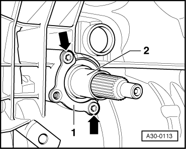
| 7 - | Guide sleeve |
| q | Removing and installing → Fig. |
| q | Before removing and installing, cover input shaft splines with a shrink-fit hose to protect oil seal |
| 8 - | Clutch release lever |
| q | Removing and installing → Fig. |
| q | Before installing, lubricate area which makes contact with plunger of slave cylinder with copper grease (commercially available). |
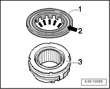
| 9 - | Release bearing |
| q | Do not wash out; wipe clean only |
| q | Renew bearing if noisy |
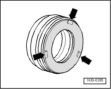
| q | Servicing release bearing with glued plastic ring → Fig. |
| q | Checking release bearing with mechanically attached plastic ring → Fig. |
| q | Renew if groove worn on plastic ring is too deep → Fig. |
| q | Retainer lugs on release bearing must engage in release lever |
| 10 - | Bolt |
| q | 24 Nm |
| q | Self-locking |
| q | Before installing bolt, clean thread with wire brush and then apply locking fluid -AMV 185 101 A1- |
| 11 - | Leaf spring |
| 12 - | Bolt |
| q | 24 Nm |
| q | Self-locking |
| q | Before installing bolt, clean thread with wire brush and then apply locking fluid -AMV 185 101 A1- |
| 13 - | Retaining piece |
| q | For guide sleeve |
| q | Removing and installing → Fig. |
| 14 - | Intermediate piece |
| q | Renew if damaged |
| 15 - | Gearbox |
|
|
|
|
|
|
|
|
|
|
|

|
|
|