| –
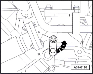
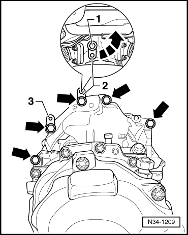
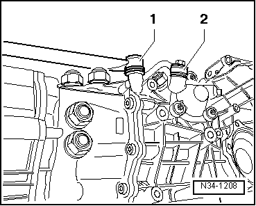
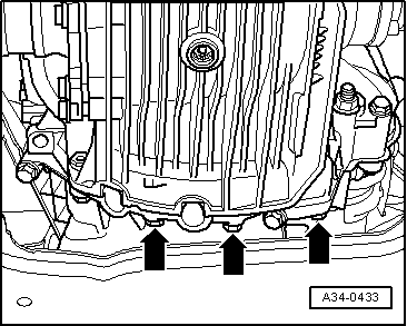
| Tighten the three lower engine/gearbox securing bolts at bottom -arrows- to torque setting. |
| The remaining installation steps are carried out in the reverse sequence; note the following points: |
| –
| Check selector mechanism setting and adjust if necessary → Chapter. |

Caution | Never use a charger to aid starting. Otherwise, the vehicle's control units could be damaged. |
|
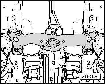
| t
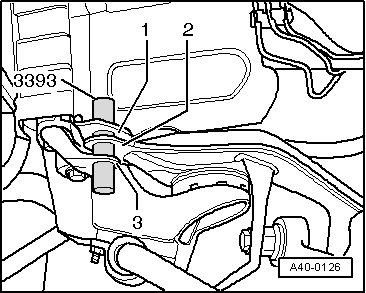
| A wheel alignment check is not necessary if the alignment of the subframe in relation to the body was checked using locating pins -3393- prior to dismantling and assembly of the subframe (before tightening bolts). |
| t
| A wheel alignment check must, however, be carried out if the alignment of the subframe relative to the body was not checked or if it was not possible to fully insert the two locating pins -3393- into the holes. |

Note | t
| Tightening torques apply only to lightly greased, oiled, phosphated or black-finished nuts and bolts. |
| t
| Additional lubricant such as engine or gear oil may be used, but do not use graphite lubricant. |
| t
| Do not use parts which have been degreased. |
| t
| Tolerance for tightening torques is ± 15%. |
|
|
|