
A4 Mk2
| Electrical/electronic components and fitting locations |
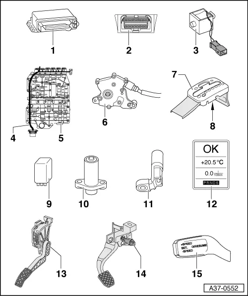
| 1 - | Automatic gearbox control unit -J217- |
| q | Fitting location; removing and installing → Chapter |
| q | Control unit is checked by self-diagnosis |
| q | Unplugging multi-pin connector → Anchor |
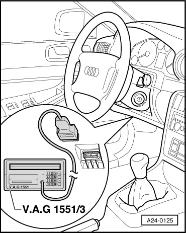
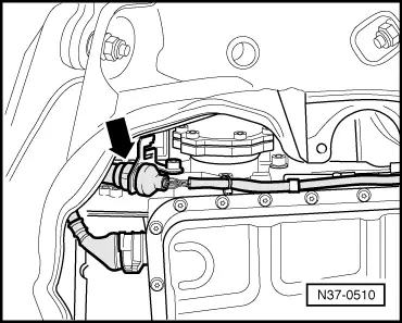
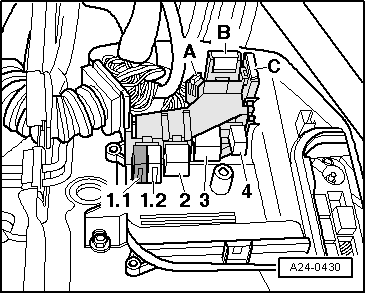
| 2 - | Diagnostic connector |
| q | Fitting location → Fig. |
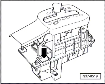
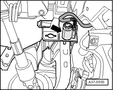
| 3 - | Selector lever lock solenoid -N110- |
| q | Fitting location → Fig. |
| q | Checked via self-diagnosis |
| q | Removing and installing → Chapter |
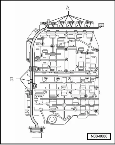
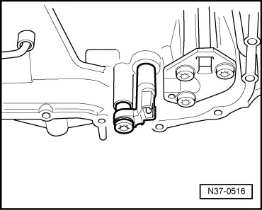
| 4 - | Wiring harness in gearbox |
| q | Gearbox oil temperature sender -G93- integrated in wiring harness |
| q | Fitting location → Fig. |
| q | Gearbox oil temperature sender -G93- is checked by self-diagnosis |
| q | Removing and installing → Servicing automatic gearbox 01V, front-wheel drive and four-wheel drive; Rep. Gr.38 |
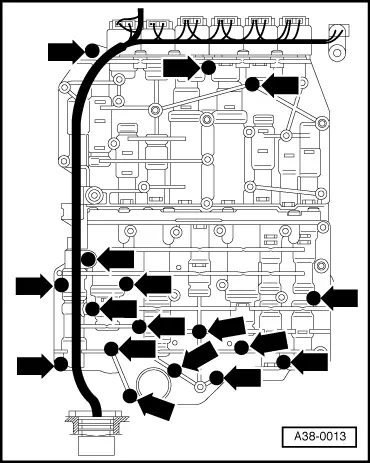
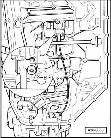
| 5 - | Valve body |
| q | Fitting location → Fig. |
| q | Components are checked by self-diagnosis |
| q | Removing and installing → Servicing automatic gearbox 01V, front-wheel drive and four-wheel drive; Rep. Gr.38 |
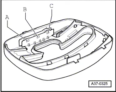
| 6 - | Multifunction switch -F125- |
| q | Fitting location → Fig. |
| q | Checked via self-diagnosis |
| q | Removing and installing → Chapter |
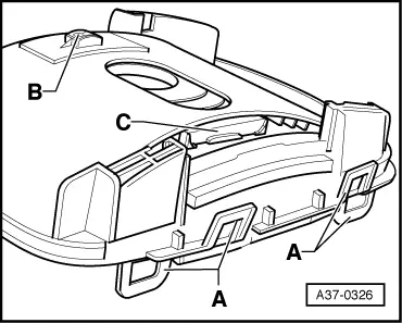
| 7 - | Selector mechanism cover |
| q | Removing and installing → Chapter |
| 8 - | tiptronic switch -F189- |
| q | Fitting location → Fig. |
| q | Checked via self-diagnosis |
| q | Removing and installing → Chapter |
| 9 - | Automatic gearbox relay -J60- |
| q | Not fitted with all engines; for allocation refer to → Current flow diagrams, Electrical fault finding and Fitting locations |
| q | Fitting location → Fig. |
| q | Checking → Chapter |
| 10 - | Gearbox input speed sender -G182- |
| q | Fitting location → Fig. |
| q | Checked via self-diagnosis |
| 11 - | Gearbox output speed sender -G195- |
| q | Measures gearbox output speed |
| q | Fitting location → Fig. |
| q | Checked via self-diagnosis |
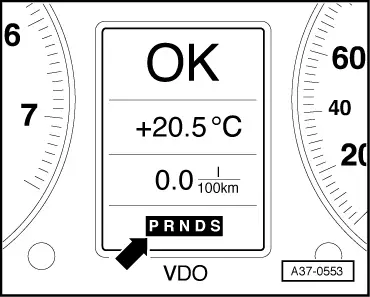
| 12 - | Selector lever position display -Y6- |
| q | Fitting location → Fig. |
| q | A fully illuminated gear selection indicator indicates a simple fault |
| q | A flashing gear selection indicator indicates a critical fault |
| q | A blank display indicates defective wiring or a defective selector lever position display -Y6-. |
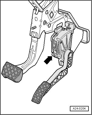
| 13 - | Kick-down switch -F8- |
| q | Not fitted as a separate component; this function is performed by the accelerator position senders in the accelerator pedal module |
| q | Fitting location → Fig. |
| 14 - | Brake light switch -F- |
| q | Signal recognition in engine control unit, signal transmission from engine control unit to gearbox control unit via CAN bus |
| q | Fitting location → Fig. |
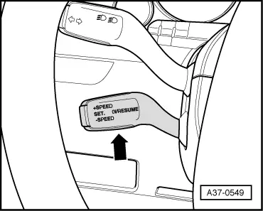
| 15 - | Cruise control system switch -E45- |
| q | Fitting location → Fig. |
|
|
|
|
|
|
 Note
Note
|
|
Note |
|
|
|
|
|
Note
|
|
|
|
Note
|
|
Note
|
|
Note
|
|
|
|