
A4 Mk2
|
|
|
|
|
 Note
Note
|
|
|
|
|
|
Note
|
|
|
|
|
|
|
|
|
|
|
|
|
|
|
|
Note
|
|
|
|
Note
|
|
Note
Note
|
|
|
|
| Component | Nm |
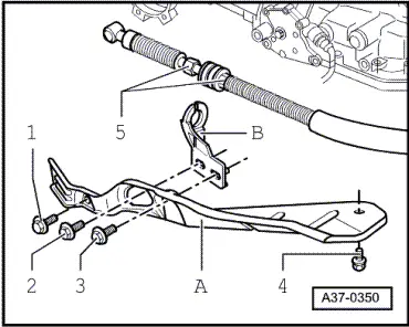
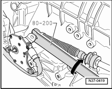
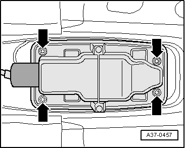
| Cover (bottom) to selector mechanism | 10 |
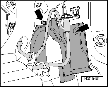
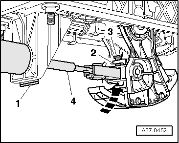
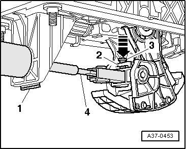
| Selector lever cable to support bracket | 12 |
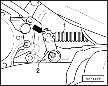
| Support bracket to gearbox | 23 |
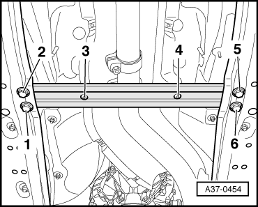
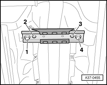
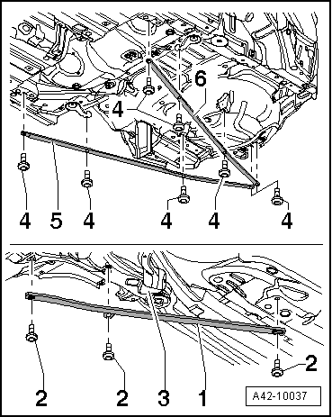
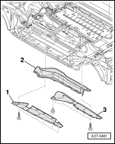
| Front cross member to vehicle underside | 55 |
| Rear cross member to vehicle underside | 55 |